The V32TTL provides 32 TTL level digital I/O lines. Lines can be individually configured as inputs or outputs.
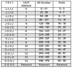
1. Install ADDR jumpers to pins 1-2, 3-4, 5-6 and 7-8 (as shipped). This puts the board at VAST address 0, with the I/O lines at bit numbers 0 through 31.
2. Connect the VAST cable to the SBC2000.
3. Execute the following code:
SUBROUTINE delay(arg AS INTEGER)
	LOCAL index AS INTEGER
	FOR index = 0 TO arg
		REM
	NEXT index
END
CONSTANT crlf AS STRING = "\013\010"
GLOBAL line AS INTEGER
REM read the state of all 32 inputs
VDIO_CONFIG(0,1)
PRINT crlf, "Start"
FOR line = 0 TO 31
	PRINT crlf, VTEST(line)
NEXT line See the Vesta Multi-Tasking Basic manual for information on how these commands are used.
| Pin | Signal | Pin | Signal |
| 1 | Ground | 2 | +5v |
| 3 | DIO 0 | 4 | DIO |
| 5 | DIO 2 | 6 | DIO 3 |
| 7 | DIO 4 | 8 | DIO 5 |
| 9 | DIO 6 | 10 | DIO 7 |
| 11 | DIO 6 | 12 | DIO 9 |
| 13 | DIO 10 | 14 | DIO 11 |
| 15 | DIO 12 | 16 | DIO 13 |
| 17 | DIO 14 | 18 | DIO 15 |
| 19 | DIO 16 | 20 | DIO 17 |
| 21 | DIO 18 | 22 | DIO 19 |
| 23 | DIO 20 | 24 | DIO 21 |
| 25 | DIO 22 | 26 | DIO 23 |
| 27 | DIO 24 | 28 | DIO 35 |
| 29 | DIO 26 | 30 | DIO 27 |
| 31 | DIO 28 | 32 | DIO 29 |
| 33 | DIO 30 | 34 | DIO 31 |
The current draw for a V32TTL is 2mA for board logic when outputs are unloaded.
Dimensions are in inches.