The V8RLYOPTO has 8 relays with SPDT contacts capable of switching 3 Amps at 120 VAC and 8 optically isolated inputs configured to detect contact closures.
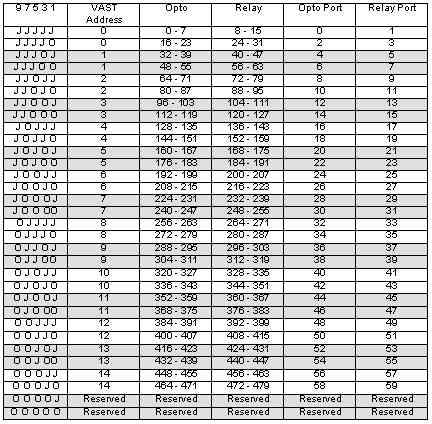
1. Install jumpers to ADDR pins 1-2, 3-4, 5-6, 7-8 and 9-10 (as shipped). This puts the board at VAST address 0, with:
2. Connect the VAST cable to the SBC2000.
3. Execute the following code:
SUBROUTINE delay(arg as integer)
LOCAL index AS INTEGER
	FOR index= 0 TO arg
		REM
	NEXT
END
CONSTANT CRLF AS STRING = "\010\013"
GLOBAL relay AS INTEGER, opto AS INTEGER
PRINT CRLF,"Start"
DO
	PRINT CRLF
	FOR opto = 0 TO 7
		PRINT VTEST(opto)
	NEXT
	FOR relay=8 TO 15
		delay(300)
		VSET(relay): delay(300)
		VRESET(relay)
	NEXT
LOOP UNTIL 0 See the Vesta Multi-Tasking Basic manual for information on how these commands are used. See "V8RLYOPTO Address Jumpers", below, for information on which bit numbers correspond with which ports.
| Pin | Signal | Pin | Signal |
| 1 | Input 0 | 2 | Ground |
| 3 | Input 1 | 4 | Ground |
| 5 | Input 2 | 6 | Ground |
| 7 | Input 3 | 8 | Ground |
| 9 | Input 4 | 10 | Ground |
| 11 | Input 5 | 12 | Ground |
| 13 | Input 6 | 14 | Ground |
| 15 | Input 7 | 16 | Ground |
| J | Relay | COM | N.O. | NC |
| 4 | 4 | 1 | 2 | 3 |
| 5 | 4 | 5 | 6 | |
| 6 | 7 | 8 | 9 | |
| 7 | 10 | 11 | 12 | |
| 5 | 0 | 1 | 2 | 3 |
| 1 | 4 | 5 | 6 | |
| 2 | 7 | 8 | 9 | |
| 3 | 10 | 11 | 12 |
Power may be supplied over the VAST cable. Typical cable loss is 150 mV per foot of VAST cable when the V8RLYOPTO is fully energized. Power may be applied directly to the V8RLYOPTO at the PWR connector. If a separate power supply is used for the V8RLYOPTO or if the coil voltage of the V8RLYOPTO is not 5 VDC, the jumper "+R" must be removed.
With all relays and opto inputs energized, the V8RLYOPTO requires approximately 1 Ampere of current at 5 VDC.
Dimensions are in inches.