The VAST 8x8 LEDis a 2.4" square matrix of 64 LEDs. The matrix display is designed to display high intensity bar graph or line graph displays.
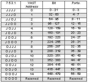
1. Install jumpers to ADDR pins 1-2, 3-4, 5-6 and 7-8. This puts the V8x8LED at VAST address 0.
2. Connect the VAST cable to the SBC2000.
3. Apply power and execute the following code:
subroutine delay(arg as integer)
	local index as integer
	for index=0 to arg
		REM
	NEXT
END

GLOBAL row AS INTEGER, column AS INTEGER
REM turn on the display, 50% intensity
VLED_COMMAND(0,15)
DO
	FOR row = 0 TO 7
		FOR column=0 TO 7
			VLED_MATRIX(column,2^row)
			delay(500)
			VLED_MATRIX(column,0)
		NEXT
	NEXT
LOOP UNTIL 0 VLED_MATRIX()
VLED _MATRIX() writes the byte of data to the digit at the specified position.
Where:VLED _MATRIX(position, byte)
Each bit of the byte controls a segment.
- "position "
- is the position of the LED in the LED matrix. Refer to the documentation for the peripheral you are using for more information.
- "byte"
- is value that you want to write.
Where:VLED_COMMAND(board, intensity)
- "board"
- is the VAST address as determined by the ADDR jumpers. Refer to the documentation on the peripheral you are using for more information.
- "intensity"
- is a byte of data encoded as follows:
D7 Test - all segments on at maximum intensity when this bit is set to zero
D6-D4 Set to 0 - not used
D3-D0 Intensity - 0=off, 15=maximum
D6-D4 must be set to zero for proper operation. Non-zero values will disable areas of the matrix. Non-zero values will cause a subset of the digits to be individually enabled, starting from the rightmost digit.
Dimensions are in inches.