The VAST 24-bit analog to digital converter (VADC24) provides six programmable, high precision inputs suitable for applications where Analog input must be converted to a digital input at a 24 bit resolution; for example, when measuring a slowly changing signal.
Differential, pseudo-differential, unipolar and bipolar sampling modes are supported. The VADC24 is equipped with programmable filtering, gain, and calibration modes. A temperature sensor is built on to the board for monitoring the temperature of your SBC2000 environment.
AIN_CONFIG()
AIN_CONFIG() selescts the peripheral you're working with and configures analog to digital
conversions.
Where:AIN_CONFIG(func, value)
- "func"
- is an integer representing the function being set. Refer to the documentation on the peripheral you are using to find out what func options are available for that peripheral.
- "value"
- is value that you want to set the function to. Refer to the documentation on the peripheral you are using to find out what values are available for that function.
| Func | Setting | Value | Configuration |
| 0 | Select Peripheral | 3 | Selects VADC24 |
| 1 | Input Organization | 0 | Pseudo-differential (default) |
| 1 | Differential | ||
| 2 | Polarity | 0 | Unipolar |
| 1 | Bipolar (default) | ||
| 3 | Gain | 0 | 1 (default) |
| 1 | 2 | ||
| 2 | 4 | ||
| 3 | 8 | ||
| 4 | 16 | ||
| 5 | 32 | ||
| 6 | 64 | ||
| 7 | 128 | ||
| 4 | Word length and Burn-out currents | 0 | 16-bit, currents off |
| 1 | 24-bit, currents off | ||
| 4 | 16-bit, currents on | ||
| 5 | 24-bit, currents on | ||
| 5 | Filter Frequency | 19 to 4000 | See input filter frequency section |
| 6 | Calibration mode | 0 to 7 | See calibration section |
| 7 | Calibration channel | 0 to 5 | See calibration section |
| 8 | Program VADC24 | 0 | Programs all of the above parameters and runs a calibration if necessary |
AIN_CONFIG() need not be called before every conversion. Once extensions are configured, they will remain so until changed to use another peripheral or power is lost.
Note: after changing configuration data, conversions results will not be accurate for three to five conversion cycles.
When the VADC24 is selected using value = 3, the rest of the conversion parameters are automatically set to a default configuration.
AIN()
AIN() reads the specified AIN channel.
Where:AIN(channel)
- "channel"
- is AIN channel you want to test. Refer to the documentation on the peripheral you are using to find out what channel options are available for that peripheral.
The return value ranges are as follows:
Bits From To Unipolar 16 bit 0 65535 Bipolar 16 bit -32768 32767 Unipolar 24 bit 0 16777215 Bipolar 24 bit -8388608 8388607
| Pin | Signal | Pin | Signal |
| 1 | Analog GND | 2 | Analog +5V |
| 3 | AIN0 | 4 | AIN1 |
| 5 | AIN2 | 6 | AIN3 |
| 7 | AIN4 | 8 | AIN5 |
| 9 | External References - | 10 | External References + |
In unipolar mode, the input differential for zero and full scale results is:
| Gain | Input differential for zero scale result | Input differential for full scale result |
| 1 | 0 | 2.5V |
| 2 | 0 | 1.25V |
| 4 | 0 | 625mV |
| 8 | 0 | 312.5mV |
| 16 | 0 | 156.3mV |
| 32 | 0 | 78.13mV |
| 64 | 0 | 39.06mV |
| 128 | 0 | 19.53mV |
In bipolar mode, the input differential for zero and full scale results is:
| Gain | Input differential for zero scale result | Input differential for full scale result |
| 1 | -2.5V | 2.5V |
| 2 | -1.25V | 1.25V |
| 4 | -625mV | 625mV |
| 8 | -312.5mV | 312.5mV |
| 16 | -156.3mV | 156.3mV |
| 32 | -78.13mV | 78.13mV |
| 64 | -39.06mV | 39.06mV |
| 128 | -19.53mV | 19.53mV |
Configuring Vesta Basic or the Vesta C library to use the VADC24, unipolar or bipolar conversions, differential or pseudo-differential conversions, input gain, input filter frequency, conversion accuracy (16 or 24 bit), and self-calibration modes is done through software using the VAIN_CONFIG() procedure. Once you have set each parameter the way you wish, you must make the procedure call CALL VAIN_CONFIG(8,0) In order to program the peripheral.
To configure for unipolar or bipolar conversions, use the polarity parameter of the Init_VADC24 procedure call.
| Parameter Value | Polarity |
| 0 | Unipolar |
| 1 | Bipolar (default) |
The VADC24 supports differential input pairs (AIN1 & AIN2, AIN3 & AIN4, AIN5 & AIN6) or pseudo-differential input pairs (AIN1 through AIN5 paired with AIN6). To configure for either organization, use the type parameter of the Init_VADC24 procedure call.
| Value of type | Organization |
| 0 | Pseudo-differential (default) |
| 1 | Differential |
| Input Gain |
| 1 (default) |
| 2 |
| 4 |
| 8 |
| 16 |
| 32 |
| 64 |
| 128 |
A programmable gain amplifier is used on all inputs. Its gain range is between 1 and 128 in powers of 2. To set the input gain for all channels, use the gain parameter of the Init_VADC24 procedure call.
Note: when you change configuration data the conversion results get temporarily disrupted and the accuracy of the next 3 or 4 conversions after a configuration change cannot be guaranteed.
Gain should be set before running any calibrations.
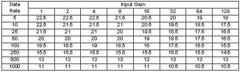
The VADC24 is equipped with a programmable input filter that controls the rate of conversions. The data rate is programmed with the freq parameter to the Init_VADC24 procedure call. Allowable values for freq are in the range from 4.8 Hz to 1010 Hz.
Note: after changing configuration data, conversions results will not be accurate for three to five conversion cycles. The choice of data rate can dramatically affect the noise of the VADC24. The following table indicates effective resolution for various data rates and gain settings.
Once the VADC24 has been configured and programmed properly, conversion results become available as often as the filter frequency setting allows. This is done by calling the following procedure:
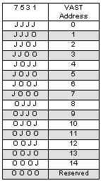
CALL AIN_VADC24(Cc)
Where Cc is the VAST address multiplied by 6 plus the number of the channel on the board to be converted.
Depending on the input organization (differential or pseudo-differential) the meaning of Cc differs according to the following table.
| Cc | Diff. Pair | Pseudo-diff. Pair |
| 0 | AIN0 vs AIN5 | AIN0 vs AIN1 |
| 1 | AIN1 vs AIN5 | AIN1 vs AIN0 |
| 2 | AIN2 vs AIN5 | AIN2 vs AIN3 |
| 3 | AIN3 vs AIN5 | AIN3 vs AIN2 |
| 4 | AIN4 vs AIN5 | AIN4 vs AIN5 |
There are eight modes of input calibration available on the VADC24. Calibration modes are selected with the following sequence of procedure calls:
CALL Calibrate_VADC24(channel, Cm)
A self-calibration should always be performed on any channel before you start conversions on that channel. A system offset calibration should always be performed as part of the board initialization.
| Cm | Type of calibration | When calibrated |
| 0x00 | Normal (no calibration) | N/A |
| 0x20 | Self-calibration | Immediately |
| 0x40 | Zero-scale system | Immediately |
| 0x60 | Full-scale system | Immediately |
| 0x80 | System offset | Immediately |
| 0xA0 | Background | Before every Conversion |
| 0xC0 | Zero-scale self | Immediately |
| 0xE0 | Full-scale self | Immediately |
The results of any calibration are stored in one of three pairs of calibration registers on the VADC24. The registers are assigned to inputs according to the following table:
| Cc | Diff. Cal. Registers | Pseudo-diff. Cal.Registers |
| 0 | Reg. Pair 0 | Reg. Pair 0 |
| 1 | Reg. Pair 0 | Reg. Pair 1 |
| 2 | Reg. Pair 1 | Reg. Pair 2 |
| 3 | Reg. Pair 1 | Reg Pair 2 |
| 4 | Reg. Pair 2 | Reg. Pair 2 |
In this mode no calibration is run. This is the powerup default. Setting this mode will disable background calibrations if they are executing.
Zero-scale and full-scale calibrations are run on internally generated voltages for the selected channel.
This performs a zero-scale calibration on the selected channel using an external voltage placed on the input. This voltage level will then be considered a zero-scale input on the selected input.
This performs a full-scale calibration on the selected channel using an external voltage placed on the input. This voltage level will then be considered a full-scale input on the selected input.
This mode performs a zero-scale calibration on an external level provided into the selected input. The result of the calibration is used as the offset of the VADC24 from the measured system.
This mode is the only calibration that is not executed immediately upon a Calibrate_VADC24 call. Instead, a zero-scale system calibration is performed before every conversion. Background calibration mode has the effect of slowing conversion times by a factor of 6.
This is the same is the zero-scale system calibration except that an internally generated zero level input is used.
This is the same is the full-scale system calibration except that an internally generated full-scale level input is used.
The data word length can be set to either 16 bits or 24 bits. This is done with the size parameter of the Init_VADC24 procedure call.
| Value of size | Word length |
| 16 | 16 bits (powerup default) |
| 24 | 24 bits |
The VADC24 is equipped with the capability of generating a current that can be used to test if the transducer providing an input to the VADC24 has gone open or short-circuit. A 1µA current is sourced on the positive leg of the input pair and sunk on the negative leg. In this state, a full-scale input reading indicates an open transducer, and a zero scale reading indicates a shorted transducer.
Burn-out currents are off at powerup. They can be turned on by OR'ing 0x02 to the op_mode parameter of the Init_VADC24 procedure call, or by OR'ing 0x02 into the cal_mode parameter of the Calibrate_VADC24 procedure call.
Burn-out currents can be turned off by calling Init_VADC24 or Calibrate_VADC24 without OR'ing a 0x02 into the op_mode or cal_mode parameter.
The VADC24 is equipped with a precision temperature sensor that can be attached to AIN1 by installing jumper 6 in the CONFIG jumper block. Note that the temperature signal is relative to analog ground.
| Temp. Range | -400 to +850C |
| Sensitivity | 1.9 mV / 0C |
| Output at 250C | 560 mV +/-60mV |
The 0V and 2.5V reference levels required by the ADC chip on the VADC24 are generated by on-board hardware. You have the option of providing your own reference levels externally (through the AIN connector pins 9 and 10). Jumpers 1-4 of the CONFIG jumper block select internal and external references. Installing jumpers 1 and 4 (and removing jumpers 2 and 3) configures the VADC24 to use internal references. Installing only jumpers 2 and 3 configures the VADC24 to use external references.
You can measure the on-board 2.5 V reference level. Installing jumper 5 of the CONFIG jumper block will short the 2.5 V reference to the input used by AIN2. You can then read the level by running a conversion on channel 1 of the board using pseudo-differential mode.
The VADC24 draws about 3 mA of current.
Dimensions are in inches.