The VADC8 provides 8 analog to digital converter inputs capable of measuring voltages between 0 and 4.095 VDC with a resolution of one part in 1024. The VAIO8 adds 8 channels of analog output with a range of 0 to 4.096 VDC (adjustable).
Warning: On our SBC2000 engines that include VAST, the LCD and keypad share some lines with the VAST connector. In most cases the VAST peripheral will interpret the signals correctly in spite of any operations involving the LCD or keypad. However, in the case of the VAIO8 board, the TLC5628 DAC chip may get confused if it happens to get just the right combination of extraneous signals. If the upper or lower four bits of a character sent to the LCD or keypad scan data happens to match the DAC's VAST address, and then the next set that do not match is interpreted by the DAC chip on the VAIO8 as a "load new value" operation, and causes new values to be loaded for all channels.
a) The easiest workaround is to use either the VAST AIODIO8 or the VAST AIO12 board instead of the VAIO8 board. If you only need one channel, use the VAST AIODIO8. If you need more than one channel use the VAST AIO12 board. These boards use different chips and don't exhibit the problem.
b) Alternatively, you can create a custom VAST cable by disconnecting the VA3 line from the cable and re-routing it to an available digital output bit on the SBC2000. Then write your application to keep the digital output bit high (at logic 1 level) at all times except when you want to communicate with the board.
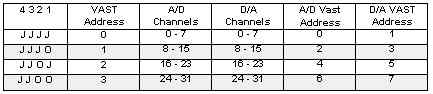
1. Install ADDR jumper pins 1-2 (as shipped). This puts the board at VAST address 0, with:
2. Install a jumper between pin 3 of the AOUT0_3 connector and pin 3 of the AIN connector. This connects channel 0 of the D/A to channel 0 of the A/D.
3. Connect the VAST cable to the SBC2000.
4. Apply power to the SBC2000 and execute the following code:
CONSTANT CRLF AS STRING = "\010\013"
GLOBAL value AS INTEGER

DO
	PRINT CRLF
	FOR value = 0 TO 1024 STEP 64
		VAOUT(0, value)
		PRINT AIN(0)
	NEXT
LOOP UNTIL 0
See The Vesta Multi-tasking Basic Manual for information on how these commands are used.
Configuration Settings for VADC8 and VAIO8
| Func | Setting | Value | Configuration |
| 0 | Select Peripheral | 1 | Selects VAIO8 |
| 1 | Input Organization | 0 | AIN0-7 are single ended input (default) |
| 1 | AIN0-1, 2-3, 4-5 and 6-7 are differential pairs | ||
| 2 | Polarity | 0 | Unipolar (default) |
| 1 | Bipolar | ||
| 4 | Powerdown mode | 0 | Full Powerdown |
| 1 | Standby Powerdown | ||
| 2 | Normal (default) |
Polarity: Single-ended conversions are unipolar only. Differential conversions can be either unipolar or bipolar.
Powerdown Mode: At the end of each command byte, the ADC is told to which powerdown mode to enter at the end of the conversion.
Full Powerdown: Consumes almost no current but takes 200ms for the chip to return to operations.
Standby Powerdown: Consumes more current and wakes quicker. The ADC chip must be fully powered to run a conversion or the results will be incorrect.
VADC8 and VAIO8 Address Jumpers
| Pin | Signal | Pin | Signal |
| 1 | AGND | 2 | +5V |
| 3 | AIN0 | 4 | AIN1 |
| 5 | AIN2 | 6 | AIN3 |
| 7 | AIN4 | 8 | AIN5 |
| 9 | AIN6 | 10 | AIN7 |
| Pin | AOUT0-3 | AOUT4-7 |
| 1 | AGND | AGND |
| 2 | +5V | +5V |
| 3 | AOUT0 | AOUT4 |
| 4 | AOUT1 | AOUT5 |
| 5 | AOUT2 | AOUT6 |
| 6 | AOUT3 | AOUT7 |
| 7 | Vrefout | Vrefout |
| 8 | Vreout | Vrefout |
The trimpot marked "ADC_CAL" is used to trim the reference of the A/D. Calibration range is 2%. While inputting a known voltage, trim until the result in millivolts or bits is equal to the input. The trimpot marked "DAC_CAL" calibrates the D/A. The D/As may be calibrated through a much larger range than the ADC. Calibrate by setting the DAC to 255 and adjust the trimpot for 2.048 Volts or the desired full scale output. Output voltages greater than 3.6 Volts will depend on the load and Vcc.
The analog inputs represent a DC load of 1 Meg Ohm. However, the AC impedance is significantly lower. Inputs should be driven from a low impedance source or a large (0.1 uF) capacitor placed from the input to ground. Each D/A is buffered with an internal operational amplifier. These op amps can drive 3.6 volts into a 10k Ohm load with negligible error. A 1k Ohm load will produce 1 LSB of error. The VAIO8 requires 3 milliamperes at 5 VDC.
Dimensions are in inches.