The VAIODIO8 provides 8 digital I/O lines, four 8-bit analog to digital converter inputs, and a single 8-bit digital to analog converter output. Full voltage range for both inputs and outputs is 5V.
Note: On our SBC2000 engines that include VAST, the LCD and keypad share some lines with the VAST connector. In most cases the VAST peripheral will interpret the signals correctly in spite of any operations involving the LCD or keypad. However, in the case of the VAIO8 board, the TLC5628 DAC chip may get confused if it happens to get just the right combination of extraneous signals. If the upper or lower four bits of keypad scan data or a character sent to the LCD happens to match the DAC's VAST address, and then the next set do not match, the DAC chip on the VAIO8 interprets the signal as a "load new value" operation, and causes new values to be loaded for all channels.
a) The easiest workaround is to use either the VAST AIODIO8 or the VAST AIO12 board instead of the VAIO8 board. If you only need one channel, use the VAST AIODIO8. If you need more than one channel use the VAST AIO12 board. These boards use different chips and don't exhibit the problem.
b) Alternatively, you can create a custom VAST cable by disconnecting the VA3 line from the cable and re-routing it to an available digital output bit on the SBC2000. Then write your application to keep the digital output bit at 1 level at all times except when you want to communicate with the board.
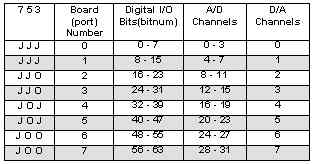
1. Install ADDR jumpers to pins 3-4, 5-6 and 7-8 (as shipped). This is an IIC peripheral, and will always be at VAST address 15. The address jumpers are used to select among more than one IIC peripheral. With the jumpers in this position:
2. Connect the VAST cable to the SBC2000
3. Execute the following code:
GLOBAL i AS INTEGER
CONSTANT crlf AS STRING = "\013\010"
VDIO_CONFIG(0,0)
REM Turn each bit on
FOR i = 0 TO 7
	VSET(i)
NEXT i

REM Read an analog input
DO
	VAIN_CONFIG(0,0)
	PRINT VAIN(0), crlf
LOOP UNTIL 0
VAIN_CONFIG() Settings for VAIODIO8
| Func | Setting | Value | Configuration |
| 0 | Select Peripheral | 0 | Selects VAIODIO8 |
| 1 | Input organization | 0 | AIN0-3 are single ended input |
| 1 | AIN0-2 are differential w/ respect to AIN3 | ||
| 2 | AIN0-1 are single ended, AIN2-3 are a differential pair | ||
| 3 | AIN0-1 and AIN2-3 are differential pairs |
| Pin | Signal | Pin | Signal | Note |
| 1 | DGND | 9 | DIO6 | AGND : |
| 2 | +5V | 10 | DIO7 | |
| 3 | DIO0 | 11 | AGND | |
| 4 | DIO1 | 12 | AOUT | |
| 5 | DIO2 | 13 | AIN0 | |
| 6 | DIO3 | 14 | AIN1 | |
| 7 | DIO4 | 15 | AIN2 | |
| 8 | DIO5 | 16 | AIN3 |
All digital lines are software programmable as inputs or outputs.
Single-ended and differential input conversions are available. In single-ended mode, the input voltage range is 0-5V. in differential mode, the voltage range is -2.5V to +2.5V with respect to each other. In no case may an input voltage be less than ground.
The VAIODIO8 draws 2 mA with the outputs unloaded for board logic and decoding.
Dimensions are in inches.