The Basics of Vesta Basic. 43
Application
Storage. 44
Memory Allocation. 44
Using the Stack as Variable Space. 44
Compiling
Without Debug. 45
Line
Format 46
Case
Sensitivity. 46
Language
Extensions and Examples. 46
Data
Types. 46
Naming Variables, Subroutines and Functions. 46
Variables. 46
Variable Initialization. 47
Arguments. 47
Subroutines. 47
Functions. 48
VITAL
Procedures. 48
Arrays. 48
Creating Arrays. 49
One Dimensional Array. 50
Additional Arrays. 50
Create a Two Dimensional Array. 50
Placing an Array at a Specific Location. 50
Arrays of Constant Data. 51
Constants. 51
Numeric Constants. 51
String Constants. 52
Mixed
Data Types. 53
Expressions with Mixed Data Types. 53
Assignments Using Mixed Data Types. 54
Intermediate Results in Computations. 54
Expression
Operators. 55
Math Errors. 55
Logical
Operators. 55
Relational
Operators. 55
Startup
Time. 55
Timers. 55
Internal
Registers. 57
Interrupts. 59
Applications for the SBC2000-074 and the SBC2000-062 will be
stored in serial EEPROM and will auto-execute upon reset. The largest program for the SBC2000-062 and
SBC2000-074 is limited by the size of the installed EEPROM, less any amount
reserved for array or data storage and 22 bytes of Vesta Basic reserved
locations.
Variable and stack space is limited on the SBC2000-062 and
the SBC2000-074.
|
SBC2000
|
Variable
|
Stack
|
|
-062
|
30 bytes
|
54 bytes
|
|
-074
|
48 bytes
|
94 bytes
|
Declaring a variable uses 1, 2 or 4 bytes of variable space,
depending on whether the variable is a byte, integer or a float. Bit variables allocate one byte of variable
space for each 8 bits.
All memory allocation can be viewed after a successful
compilation with the IDE menu item View|Program Info. When examining
this report, remember that in order to calculate total stack usage, you have to
add together the stack requirements of procedures that are called by other
procedures.
Any array that is placed at a specific location is not
accounted for in EEPROM usage when viewing the program info report. Certain types of data (e.g. arrays,
READ/DATA), are stored in the EEPROM.
EEPROM memory has a life of at least 1,000,000 program
cycles. This limitation is important to
keep in mind if you create a program that stores repetitive data, such as
tracking operations at one-second intervals.
At this rate the EEPROM will reach the end-of-life in less than 2
weeks. Infrequently used variables can
be conveniently stored as a single element array.
The stack is used to pass arguments to procedures, hold the
intermediate results of computations and retain return addresses. A subroutine call uses 4 bytes of
stack. A function call uses 6 bytes of
stack if it returns an integer, 8 if it returns a float. Built-in procedures also use stack space as
they execute.
If your
program requires no more than one or two levels of subroutine nesting, most of
your stack space goes unused. You may also want more global variables than will
fit in the available space. With
revisions 4 and later of Vesta Basic, a compiler option allows global and static
variables to "spill into" stack space. This option, like the "compile without debug" option,
must be re-enabled each time the IDE is invoked. By default, it is not enabled.
There are
some things to keep in mind any time you nest procedure calls, and particularly
when you put global variables into the stack RAM. The first is that the program information report provided by the
compiler lists worst-case stack depths for each routine, but it does not and
cannot tell you how much stack space your application will use when
running. You will have to calculate
your stack usage based on the information in this report, so you know how much
of the stack RAM you can safely use for global variables.
For
example, if the main routine calls subroutine A, which takes 10 bytes. A calls function B, which takes 20 bytes,
for a total of 30 bytes. A also calls
subroutine C, taking 12 bytes. C calls
D, which takes 10 bytes, for a total of 32 bytes. The main routine also calls E, which takes 6 bytes, so 32 bytes
is worst-case stack depth.
Also, you
must realize that using event handlers (ON COM, ON TIMER, ON INT, ON ERROR and
the debug monitor when compiled with debugger on) in your application means
that you must add the stack usage of your worst-case event handler subroutine
to the worst-case stack usage you have calculated. This is because events are
asynchronous to your application, so you don't know exactly where you are in
your application when the event occurs.
So if you had event handler subroutines F (12 bytes) and G (8 bytes),
you would have to add 12 bytes to the 32 bytes above, for a total of 44 bytes
stack usage.
When you
have enabled error handling in your application by installing an error-handling
subroutine with the ON ERROR statement, a stack overflow error will be detected
and handled when only 10 bytes of the total stack space are left. This is not adjusted for any global
variables spilled into stack RAM. Four
of these bytes will be used for subroutine return information when the error
handler is invoked. The other six bytes
are intended to provide some minimal amount of stack space for evaluating
simple statements in the error handler. This means that virtually all stack RAM
is written when a stack overflow event occurs.
One way to
detect whether the stack is overwriting variables that have been "spilled
into" stack space is to declare a variable that is not required by the
application itself just before the first line of code in your application's
main procedure. Put a known value such
as 0xAA55 into this variable, and check that the value remains unchanged each
time through your main loop. If it
changes, you know that the stack has overwritten at least that variable, and
perhaps others. If you don't use STATIC
variables in your subroutines and functions, you can do this with a global
variable. If you do use STATIC variables, the best way to check is to add a
procedure like the following one just before the first line of code in your
main routine. This is because the
compiler allocates STATIC variables after all GLOBAL variables have been
allocated.
FUNCTION Variables_Bad(operation AS BYTE) AS INTEGER
STATIC last_variable AS INTEGER
IF operation
last_variable
= 0xAA55
ENDIF
Variables_Bad =
(last_variable <> 0xAA55)
END
Call it
with a non-zero argument during your initialization, then put code in your main
loop on the order of:
IF Variables_Bad(0)
REM Appropriate actions here
PRINT
"\013\010Error: GLOBAL/STATIC variables overwritten by stack!"
DO WHILE 1
REM Lock up the system
LOOP
ENDIF
This is a
technique you should use during development, since there is nothing you can do
to recover the previous RAM values. If
you determine that the stack is overwriting your "spilled" variables,
you will need to rewrite your code to require fewer global variables or reduce
stack depth. Here are some ideas:
1. If a variable is written only once and never
changes after that, declare it as a CONSTANT.
2. Use the smallest variable type that will
work. If you only need yes/no information, use a BIT variable. If your value
will be in the range 0-255, use a BYTE.
3. Trade code space for stack depth. Rather than
call a subroutine, include the code of the subroutine in-line in your
application. This works best when the subroutine you are in-lining does not use
many local variables.
4. Break complicated expressions into several
simpler expressions. The two statements:
A = B + C
A = A * 5
take more
execution time and code space, but less stack space than
A = 5 * (B + C)
5. Compile without debug. This has no effect on
the SBC2000-062, but will save 4 bytes of global RAM on the SBC2000-074.
In general,
if your program suddenly exhibits aberrant, unexplainable behavior, suspect a
stack problem.
If Disable Debugger is selected in the Tools|Debugger
window, the program cannot be watched or animated and can only be stopped using
Debug|Stop. Programs compiled
without debug execute slightly faster (10%), save approximately 800 bytes of
application code space, and on the SBC2000-074, about 4 bytes of RAM. When testing execution speed, set the
polling rate to zero as this will be the case when the system is in operation
and the IDE is disconnected.
Always disable debug if you are going to use the DEV port as
a general purpose RS-232 port in your application.
Spaces are ignored.
When multiple statements share a single line, they must be separated by
colons. Statements that must be the
only statement on a line are as follows:
IF ELSE ENDIF LOOP
WHILE SELECT CASE FOR
FUNCTION END DO LOCAL
STATIC GLOBAL ENDSELECT
UNTIL NEXT SUBROUTINE
DECLARE CONSTANT INCLUDE
Vesta Basic is not case sensitive. In other words, "IF," "If," and
"if," are equivalent. To make
code more readable, we recommend entering all keywords and built-in procedure
calls in upper case.
Language extensions specific to the SBC2000-074 and
SBC2000-062 are on your CD-ROM in the \Examples\Vesta ST Basic\VSTB
Extensions folder. Many examples of keyword usage and application examples
can be found throughout the directory.
Vesta Basic recognizes four data types for the SBC2000-074
and three for the SBC2000-062. The data
types and their capacities listed in the chart below.
|
Type
|
Storage
|
Range
|
074
|
062
|
|
Bit
|
1 bit
|
0 or -1
|
U
|
U
|
|
Byte
|
8 bit
|
0
to 255
|
U
|
U
|
|
Integer
|
16-bit signed integer
|
-32,768 to 32,767
|
U
|
U
|
|
Float
|
Single precision (32 bits)
|
+/-1.7 x 10 +/-38 (6.5 significant
digits)
|
U
|
|
Operations on
integers truncate, rather than round decimals. Adding 1 to 32767 results in
-32768.
Byte variables are treated as the least significant byte of
an integer data type bounded between 0 and 255.
Bytevar = 255 + 1 will result in zero
Bit variables will return integer values of 0 or -1. Assigning a non-zero value to a bit variable
is equivalent to assigning a -1 to it.
Bitvar = 10
will result in bitvar value of -1
The name of a variable, subroutine or function must begin
with an alphabetic character (a thru z or A thru Z). A total of 30 alphanumeric characters (chosen from A thru Z, a
thru z, 0 thru 9 and underscore) may be used to complete the name. The variable names "VAR,"
"Var" and "var" refer to the same variable. The name of the
variable, subroutine or function is not case sensitive. If too many characters are used in a name, a
compiler error message will result.
Names cannot be identical to Vesta Basic keywords or Vesta Basic
built-in procedures.
Undocumented keywords exist in Vesta Basic to communicate to
the IDE. Do not name a variable or procedure starting with "IDE".
Variables must be declared before they are used. Declaration establishes the storage class
and the data type of the variable.
There are three storage classes you can use:
GLOBAL: Procedures may or may not have access to
global variables, depending on where in the source they are declared.
LOCAL: Declared in functions and subroutines only.
Bit variables may not be declared.
STATIC: Declared in functions and subroutines only.
The contents of the variable are retained after the procedure is completed.
Global variables are usually declared just before the main
procedure (which starts with the first executable statement). They cannot be
declared after any executable code in the main routine. This means that code within a procedure will
not have access to a global variable that is declared after the procedure is
defined. By declaring the global after
all procedures, the programmer can assure that information contained in the
procedures and the main program will not be shared.
If you need to have access to a global variable within a
procedure, that variable must be declared before the first procedure that
references it. A good practice is to
designate, at the beginning of your code, a small set of global variables that
must be accessible to all procedures. Declare the remainder of the global
variables just before the main procedure.
The best practice is not to use global variables in procedures. Instead, pass values to procedures as
needed.
There is a fourth class of variable called the formal
variable, which is created as the formal argument to a procedure. This is a local variable that is initialized
to the value of the arguments of the calling routine.
Variables of global scope (GLOBAL) and variables of local
scope (LOCAL, STATIC, and formal variables) can have the same name, belong to
the same category, and still be distinct from each other. The local variable can be used only inside
the procedure that declares it. The global variable can be used everywhere
else. However, this practice is
confusing and therefore discouraged.
Example:
SUBROUTINE
foo()
LOCAL var1 AS INTEGER :REM Distinct from global var1
var1 = 1 : REM Only changes local var1
END
GLOBAL var1 AS INTEGER
Variables are initialized to zero. GLOBAL and STATIC variables are initiated when the board is
powered-up or rebooted. Local variables
are initialized on every invocation of the procedure that declares them. Array variables are never initialized.
Subroutines and functions may require a list of
arguments. These arguments are copies
of the data being passed to the procedure by the calling procedure. The list of
arguments creates the formal variables used by the procedure. Therefore, the variable
declaration rules apply:
SUBROUTINE waveform (freq AS INTEGER)
SUBROUTINE short_tone(freq AS INTEGER,
duration AS INTEGER)
Begin subroutines with the SUBROUTINE keyword, followed by
the name of the subroutine, followed by the names and data types of any
arguments that will be passed to the subroutine enclosed in parentheses. Subroutines must end with the END
statement. Subroutines cannot return
arguments. You may exit subroutines at
any point in the routine, with the RETURN statement.
SUBROUTINE name (argument[,s] AS type)
Note that the arguments used to pass values to the subroutine
behave like local variables that have been initialized by the calling routine.
SUBROUTINE tone (freq AS INTEGER, duration AS INTEGER)
LOCAL I AS INTEGER
BEEP(freq)
FOR I = 1 TO duration
REM Can't have empty loops
NEXT I
BEEP (0)
END
Invoke the subroutine with the subroutine name or the
optional CALL statement, followed by the subroutine name. Subroutines must be called with arguments of
the corresponding types.
CALL tone(333, 400) generates a short beep at 333Hz.
CALL tone(333.0, 400) converts the float constant to an integer.
A subroutine may invoke other subroutines, functions or
itself. In order for another procedure
to invoke a subroutine, the subroutine must either be placed before the
invoking procedure in the program code, or the subroutine must be declared at
the beginning of the program, using the following syntax:
DECLARE SUBROUTINE name
Neither the keyword SUBROUTINE nor the name you assign to the
subroutine are case sensitive.
Subroutines are designed to "encapsulate
information". By passing the
subroutine a copy of the variables to serve as its list of arguments, the
subroutine cannot modify the original variables. With this method, program behavior is more structured and
self-contained. Subroutines do not
return a value, and therefore are best suited for output routines such as
PRINT, BEEP, or POKE. If you want to
give a subroutine access to a global variable, the global variable declaration
must precede the subroutine definition.
Define functions with the FUNCTION keyword followed by the
name of the function, the names and data types of any arguments passed to the
function, and a type specifier indicating what type of value the function will
return. To return values from
functions, assign the value to the function name. Functions must end with the END statement. You may exit functions at any point in the
routine, by using the RETURN statement.
FUNCTION name (argument[,s] AS type) AS type
Note that the list of arguments used to pass values to the
function is similar to local variables that have been initialized by the
calling routine.
FUNCTION square_root (num AS FLOAT) AS FLOAT
square_root = num ^ 0.5
END
There are two ways to invoke the function:
Example:
1. Assign its return value to a variable.
result = square_root (x)
2. Use the return value in an expression.
result = 7+square_root (9)
Functions may invoke other functions, subroutines, or
themselves. In order for another
procedure to invoke a function, the function must either be placed before the
invoking procedure in the program code or the function must be declared at the
beginning of the program, using the following syntax:
DECLARE FUNCTION
name AS type
Neither the keyword FUNCTION nor the name that you assign to
it is case sensitive.
Functions are designed to "encapsulate
information". By passing the function a copy of the variables to serve as
its list of arguments, you prevent the function from modifying the original
variables. With this method, program
behavior is more structured or self-contained.
If you want to give a function access to a global variable, the global
variable declaration must precede the function definition.
Declare functions or subroutines as VITAL by preceding the
FUNCTION or SUBROUTINE keyword with the modifier.
VITAL declarations will prevent the system from responding to
ON events before the procedure is completed.
Sources of events that may be deferred until the procedure is complete
are the following: interrupts,
communication events, timer events and run-time errors.
The SBC2000-074 supports arrays of byte, integer and float
data in EEPROM. The SBC2000-062
supports arrays of byte or integer data in EEPROM.
|
|
SBC2000
|
Array element size
|
|
-074
|
-062
|
|
Byte
|
U
|
U
|
1
|
|
Integer
|
U
|
U
|
2
|
|
Float
|
U
|
|
4
|
Arrays may be of either one or two dimensions.
Array indices start at 0 and are of type INTEGER. The DIM statement establishes the range of
the index or indices. If access to an
array is outside this range, a run-time error will not be produced. Therefore, be careful to access data only
within the array. On the SBC2000-074 and SBC2000-062, access to out-of-bounds
array elements is not checked and operation will continue with probably
unfortunate results.
Individual array elements may be passed to procedures as
arguments. If desired, an entire array
may be made accessible to a procedure by declaring the array before the
procedure.
Arrays are stored in EEPROM.
Array data is not zeroed upon reset.
 Note the use of square brackets to denote
array indices.
Note the use of square brackets to denote
array indices.
Do not use array variable storage for variables that
change frequently. The lifetime of an
EEPROM location is 1,000,000 write cycles.
If you change the value every second, the lifetime will be exceeded in
less than two weeks.
The creation of an array is a one or two step process.
1. Declare the array
before any procedures that will reference the array. If no procedures reference the array this step may be omitted.
2. Dimension the
array; specifying its name, indices, data type and optionally specify its
location.
The following statements create a one dimensional array of
256 elements.
DECLARE x AS INTEGER ARRAY
(... any procedures ...)
DIM x[256] AS INTEGER
The declare step allows procedures to access the array and is
optional. The dimension statement
allocates 512 bytes of EEPROM, establishes the array organization (one
dimensional), the data type (integer) and its location in memory (in this case
the location will be the default, immediately following code space).
If you recompile and reload a program, you can’t presume that
any data in an array that was stored during a previous run will still be
available.
Dimension parameters are constant and cannot be dynamically
allocated after compilation.
If subsequent arrays are needed, additional DIM statements
are needed to establish the organization, type and location of these arrays.
DIM y[256] AS INTEGER
To create a two dimensional array simply use two indices
within the square brackets.
DIM xy[10,20] AS INTEGER
Two dimensions are the maximum allowed.
Arrays may be located at a specific location in EEPROM. Unless a location is specified, arrays will
be located immediately after the program.
Placing an array of data at a later location allows the program to
change size (during development) without forcing you to continually change the
location of the array (and lose it's data).
The following statement allocates 512 bytes of storage starting at
location 0x1000.
DIM samples[256] AS INTEGER = 0x1000
 The length of application code in EEPROM is
held in bytes 16 and 17 of EEPROM. The
application code itself begins at byte 22.
Therefore, we can compute the next available byte using the following
formula:
The length of application code in EEPROM is
held in bytes 16 and 17 of EEPROM. The
application code itself begins at byte 22.
Therefore, we can compute the next available byte using the following
formula:
next_avail_byte = DPEEK(16) + 22
If you place an array at a specific location
and that location contains your basic application, your program will die as
soon as you write to that array.
The SBC2000-074 and SBC2000-062 allow arrays of constant data
to be created. This saves memory space
compared to the READ / DATA structure.
DIM array_of_const [10] AS INTEGER CONSTANT = [
0,1,2,3,4,5,6,7,8,9]
Note: The DIM
statement for a constant array, from the DIM keyword, to the opening bracket of
the constant list, must appear upon a single line. The list of values contained in the constant array may span as
many lines as needed.
Constant arrays may not be assigned to a specific location.
The range of an integer constant is -32,768 to 32,767. Integer constants can be expressed in
decimal or hexadecimal format. When
expressed in hexadecimal, the number must be preceded by the symbol 0x (a zero,
and a lower case "x"), followed by up to four hexadecimal digits.
These digits may be 0 thru 9 or A thru F. The A thru F are not case sensitive.
Floating point constants may be expressed in two ways: In standard exponential form scientific
notation (e.g., +3.14159E+0) or standard decimal format (e.g., 3.14159). The range of floating point constants is
+/-1.7 x 1038. The accuracy of floating point numbers is
more than 6.5 significant digits. For
example, if the number 1,234,567 is assigned to a floating point variable, the
result will be greater than 1,234,565 and less than 1,234,570 (do not include
commas when entering numbers).
A single character ASCII constant may be expressed by
enclosing the single character in single quotes to return the ASCII value of
that character (x='A' would result in x containing 65).
In the following example:
IF key='A' OR key='a'
IF key=65 OR key=97
...both statements are logically equivalent, but the first
one is easier to understand.
A literal string is any text enclosed in double quotes.
Example:
PRINT "Hello World"
The text strings may contain special characters known as
escape sequences, which embed certain control characters in the string. Control characters may be inserted into any
string by preceding the three digit decimal value with a backslash.
Sequence Meaning
\010 line feed
\013 carriage return
\012 form feed
\009 tab
\007 bell
See Appendix A
at the back of this manual for a compete list.
Example:
CONSTANT crlf AS STRING = "\013\010"
When integer and float data types are mixed, the programmer
should keep in mind that the order of operations will affect the speed and accuracy
of the calculation.
Integer math is about two to three times as fast as floating
point math. As long as the result of
the calculation is within the integer data limits, collecting all of the
integer operations together will result in faster calculations.
When a calculation involves only integers, the result will be
stored as an integer and any decimal portion of the number will be
truncated. This is true of intermediary
values as well as the final result.
Parentheses may be used to control the order of operations and ensure
the precision of intermediary results.
Expressions are evaluated in order of mathematical
precedence, from left to right.
Ans1 = 1 / 3 * 3.0 :REM evaluates to 0
 Ans2 = 3.0 * 1 / 3 :REM evaluates to 1.0
In the example above, the evaluation of ans1 is broken down
into two parts. Since 1 / 3 is
comprised of only integer values, the intermediate answer evaluates to an
integer and the decimal portion is truncated, resulting in a zero. The second part of the equation becomes 0 *
3.0, which also evaluates to zero.
The evaluation of Ans2 is processed in the same way, except
that the first value is now a float.
The first part of the equation, 3.0 * 1 evaluates to 3.0 because float
is more precise data type. The
intermediate answer is combined with the second half of the equation,
expression becomes 3.0/3 and the answer is 1.0.
It is possible to assign an expression of one data type to a
variable of a different data type. The
only limitations are based on the ability of the receiving variable to hold the
value of the expression. For example,
the compiler will generate an error if a float constant value that is outside
the limits of the maximum integer value, is assigned to an integer variable.
intvar = 1000000 results in a compiler error
Assigning a float constant to integer variables is permitted,
but the variable will contain only the integer portion of the truncated
floating constant. The floating-point
number is not rounded to the nearest integer before the value is truncated.
intvar = 3.9 results in intvar containing 3
During run time, a mixed data-type assignment will produce
the same results as during compile time.
No errors will be generated if the receiving variable is not large enough
to hold the assigned data. Instead, the
upper or lower limit of the data type will be stored.
floatvar = 1000000
intvar = longvar
REM results in intvar containing 32,767
intvar = 10 - .1
REM results in intvar containing 9
It is possible to have the result of a mixed data-type
expression assigned to a variable of a different type. In this case, before being stored in the
receiving variable, the expression is evaluated according to the rules
governing the mixed data-type expression. The result is converted according to
rules governing mixed data-type assignments.
For example:
floatvar = 2/3
results in floatvar containing 0.0 because the result of the
integer division is 0.
floatvar = 2/3.0
will result in floatvar containing 0.666 . . . because the
integer 2 will be promoted to a float 2.0, and the division will have a
floating point result.
Vesta Basic supports the following math operators:
+ add
- subtract and unary minus
* multiply
/ divide
\ modulus (remainder)
^ exponentiate
Programmers must remember to take into account the data range
when using math operations on integer types. These data types are stored as
16-bit signed integers. Operations are
performed as 2's complement. Adding 1
to +32,767 will result in -32,768 for an integer variable.
Unary minus is supported, unary plus is not supported. PRINT +1 will generate a compiler error.
Dividing by zero results in a run-time error. A run-time error also will result if an
attempt is made to raise a negative floating-point number to a power using
exponentiation operator (^).
Run-time math errors result in an ON ERROR event. See "Handling
EventsHandling
Events" on page 78.
Vesta Basic supports the following bitwise logical operators:
AND returns TRUE if both corresponding bits
are true
OR returns TRUE if either corresponding
bit is true
XOR returns TRUE if either but not both bit
is true
NOT inverts all bits and returns the result
Vesta Basic supports the following relational operators:
= equality
> greater than
< less than
>= greater than or equal to
<= less than or equal to
<> not equal
An expression is considered
"true" if nonzero and "false" if zero. The relational operators return all bits set
(-1) if true and all bits cleared (0) if not true.
Unary and special operators
(- and NOT) have the highest precedence, followed in order by:
• exponentiation
• multiply, divide and modulus
• add and subtract
• all logical operators
• all relational operators
Parentheses may be added to control or modify the order of
evaluation. It is considered good
coding practice to use parentheses liberally to clarify evaluation sequences.
The special operators;
MIN MAX ABS
COLS_OF ADDR_OF ROW_OF
have equal precedence to "-" and "NOT".
Vesta Basic executes several self checks before executing the
first statement of your application.
This process takes approximately 250 milliseconds.
 The three hardware counter/timers on your
SBC2000 are provided by the processor, and are distinct from the Vesta Basic
“TIMER0” and “TIMER1” timers. Although
these timers are called Timer0, Timer1, and Timer2 in the Microchip Technology
documentation, we will refer to them as TimerA, TimerB, and TimerC here to help
dispel any confusion.
The three hardware counter/timers on your
SBC2000 are provided by the processor, and are distinct from the Vesta Basic
“TIMER0” and “TIMER1” timers. Although
these timers are called Timer0, Timer1, and Timer2 in the Microchip Technology
documentation, we will refer to them as TimerA, TimerB, and TimerC here to help
dispel any confusion.
TimerA is used to create the software UART associated with
the DEV connector. It also serves as
the "system clock", generating a timebase of 10 milliseconds used by
the ON TIMERx interrupts.
 Caution: The default baud rate of the DEV port is
9600. If you change this baud rate, the
timebase of the system clock will change by the inverse factor. For example, if you halve the baud rate to
4800 you will also double the timebase from 10 milliseconds to 20 milliseconds.
Caution: The default baud rate of the DEV port is
9600. If you change this baud rate, the
timebase of the system clock will change by the inverse factor. For example, if you halve the baud rate to
4800 you will also double the timebase from 10 milliseconds to 20 milliseconds.
The second timer, called TimerB, is associated with the Real
Time Clock. TimerB oscillates at 32.768
kHz and can be useful for timing short events.
Access to this timer is documented under Real Time Clock in the
Procedures section. Some procedures
such as COUNT use this timer. This
timer is also used as the "time-out timer" for INPUT, RX and INKEY.
A third counter, TimerC, is associated with the PWM pin. An example of how to use this is contained
in the PWM.txt file found in the \Examples directory. This is used to generate audio or PWM control signals.
 Here are a few technical details that may
prove useful. Due to the limited number
of variable locations, knowing where to find a spare byte or two of RAM may be
a lifesaver.
Here are a few technical details that may
prove useful. Due to the limited number
of variable locations, knowing where to find a spare byte or two of RAM may be
a lifesaver.
|
Address (Hex)
|
Description
|
|
29
|
This register contains the timeout for RX,
COM and INPUT. If you do not use any
of these keywords, you can use this register. Non-zero values become the timeout in 1/128 second units.
|
|
2A
|
Contains the last character received by
the COM port.
|
|
2B, 2C
|
These Registers may be used if you have
compiled without debug.
|
|
31
|
This register contains the last character
received by the DEV port.
|
|
Address (Hex)
|
Bit
|
Description
|
|
81
|
6
|
Select rising (1) / falling (0) interrupt
edge for ON INT.
|
|
81
|
7
|
Disable (1) all internal pull up resistors
on Port B. Do not use KEYPAD if
resistors are disabled.
|
|
B
|
3
|
Enable / Disable ON INT interrupt.
|
|
B
|
4
|
Enable / Disable RxA interrupt (DEV port).
|
|
B
|
5
|
Enable / Disable TimerA interrupt. Kills
DEV, ON TIMER.
|
|
B
|
7
|
Enable (1) / Disable (0) all interrupts.
|
|
8C
|
0
|
Enable / Disable RTC interrupt, kill RTC,
timeouts.
|
|
8C
|
5
|
Enable / Disable COM receive interrupt.
|
 Vesta Single Tasking Basic supports
interrupts, called "events".
On the Basic level, interrupt processing can be suspended using the
VITAL keyword. However, applications
that require more dependable timing may benefit from a more absolute suspension
of interrupt handling.
Vesta Single Tasking Basic supports
interrupts, called "events".
On the Basic level, interrupt processing can be suspended using the
VITAL keyword. However, applications
that require more dependable timing may benefit from a more absolute suspension
of interrupt handling.
At the machine code level, interrupts may be disabled
completely, so that all interrupts are suspended and the interrupt handler is
not invoked at all. An interrupt
control bit is located at port 11, bit 7.
You can disable all interrupts by  writing a zero to this location.
Caution: Do this carefully and briefly. You will be unable to execute any statements
that depend on active interrupts (INPUT, PRINT, RX, TX). Also, the time of day registers may be affected,
since they are updated by the real time clock interrupt that occurs once per
second.
Turning interrupts
off will have the following effects:
1. The system
clock will stop, thus any ON TIMER statement will be suspended
2. DEV port
communication, both in and out, will cease.
3. An incoming
character to the UART (SBC2000-074) will not be read.
4. The Real Time
Clock registers will not be updated if TimerB overflows on the second.
5. Hardware
events on pins 5-8 of the keypad connector will not be recognized.
Table of Contents
Assignment 62
Global, Local, Static. 62
GLOBAL. 62
LOCAL. 62
STATIC.. 63
Bit Variables. 63
LET. 63
CONSTANT. 65
REM.. 65
INCLUDE.. 66
Procedures. 68
[VITAL], SUBROUTINE, [RETURN], END.. 68
FUNCTION.. 68
END.. 69
VITAL. 69
DECLARE.. 69
Flow Control 71
IF, [ELSE], ENDIF. 71
SELECT, CASE, [ELSE], ENDSELECT. 71
DO WHILE, [EXIT], LOOP.. 72
DO, [EXIT], LOOP UNTIL. 72
FOR [STEP], [EXIT], NEXT. 72
EXIT. 73
PRINT. 74
INPUT. 75
Operator I/O.. 76
PIPE.. 76
DATA, READ, RESTORE.. 76
DIM.. 77
Handling Events. 78
SET TIMERx TO, ON TIMERx. 78
ON ERROR.. 80
SET INT0, ON INT0. 80
SET COMx TO, ON COMx. 81
Program Control 83
STOP.. 83
REBOOT. 83
These statements define the storage class of a variable.
A. Storage class
statements that are appropriate in the main procedure.
1. GLOBAL
B. Storage class
statements that are appropriate inside subroutines and functions.
1. LOCAL
2. STATIC
The GLOBAL keyword allows you to declare a variable that can
be accessed from a later point in the program.
GLOBAL name AS type [,name AS TYPE]
¨ Global
variables are usually declared just before the main procedure (the first
executable statement.) They cannot be
declared after the first executable statement in the main procedure. This means that a procedure will not have
access to any global variable declared after the procedure is defined. By declaring the global after all
procedures, the programmer ensures separate encapsulation of information within
the procedures and the main program.
¨ If
you require access to a global variable within certain procedures, the global
variable must be declared before the first procedure that references it. A good practice is to declare, at the
beginning of your code, a small set of global variables that must be shared,
and declare all others just before the main procedure. The simplest solution is not to use global
variables in procedures if possible.
Instead, pass values to procedures as needed. At application startup,
global variables are initialized to zero.
¨ GLOBAL
variables are allocated from global RAM space. An integer requires 2 bytes of
RAM, a float requires 4 bytes of RAM, and byte variables require 1 byte of
RAM. Bit variables occupy one bit of
RAM.
Example:
GLOBAL var1 AS INTEGER, var2 AS INTEGER
¨ This
statement declares two integer variables named var1 and var2. This declaration
cannot be inside a function or subroutine definition and it cannot occur after
any executable code in the main procedure.
The LOCAL keyword allows you to declare a variable that can
be accessed within a function or subroutine, but not outside of it.
LOCAL name AS type [, name AS TYPE]
¨ The
value of a variable declared with LOCAL is set to zero each time the function
or subroutine is entered.
¨ This
declaration must be inside a function or subroutine definition, and it cannot
occur after any executable code in the function or subroutine.
¨ Local
variables are only accessible by the subroutine or function that declared them.
No other procedures can reference that particular variable. Local variables may not be of the BIT type.
¨ LOCAL
variables are allocated from stack space.
An integer requires 2 bytes of stack, a float requires 4 bytes of stack.
Example:
LOCAL variable_1 AS INTEGER
¨ Declares an
integer variable by name variable_1.
The STATIC keyword allows you to declare a variable that can
be accessed within a function or subroutine, but not outside it. A static variable retains its contents after
the procedure is completed.
STATIC name AS type [, name AS TYPE]
¨ The
value of a variable declared with STATIC will be preserved until the next time
function or subroutine is entered.
Static variables are local variables that retain their contents between
calls to the procedure.
¨ At
startup, static variables are initialized to 0.
¨ Static
variables must be declared inside the function or subroutine definition and
before any executable code in the function or subroutine.
¨ STATIC
variables are allocated from global RAM space.
An integer requires 2 bytes of RAM, a float requires 4 bytes of RAM.
Static variables may also be of the BIT type.
Example:
STATIC varb_1 AS INTEGER
declares an integer variable by the name varb_1.
Bit variables have only two states, 0 and non-zero. There are two forms of this statement: one
creates a bit variable, the other creates a bit variable associated with a
physical pin, or with a bit in one of the processor’s internal registers.
GLOBAL name AS BIT [,name AS BIT]
GLOBAL pin1 AS BIT = PORT, BIT
¨ The
bit variable is assigned a "false" value by setting the variable
equal to zero. The variable is assigned
a "true" value by assigning a non-zero value to the variable.
¨ When
the first bit variable is declared, 1 byte of RAM is allocated. When the 9th
bit variable is declared, the 2nd byte is allocated.
¨ Bit
variables may be used to control an IO location by declaring the IO location a
named bit variable and subsequently assign values to or read from the variable.
¨
Bit variables that are IO specific do not allocate
RAM.
¨
Reading from an IO bit will automatically configure is
as an input. Writing to an IO bit will
configure it as an output.
Example 1:
GLOBAL flip_flop AS BIT
DO
flip_flop = NOT flip_flop
LOOP UNTIL 0
Example 2:
GLOBAL pin1 AS BIT = 6,3
CONSTANT high AS INTEGER = -1
CONSTANT low AS INTEGER = 0
DO
pin1 = high
pin1 = low
LOOP UNTIL 0
IF pin1 = high
PRINT "pin 1 is high"
ELSE
PRINT "pin 1 is low"
ENDIF
This example identifies port 6, bit 3 as a bit variable named
"pin1". The first part of the
example shows how to set the output state using bit variables. The second part shows how to read the input
state of the pin.
The LET statement is used to assign the result of an
expression to a variable.
[LET] variable = expression
¨ It is an optional keyword provided
for compatibility with previous implementations of BASIC.
Example:
GLOBAL var_1 AS INTEGER
LET var_1 = 99
The CONSTANT declaration permits the programmer to name
values that will be reused and will not change.
CONSTANT name AS TYPE=value
¨ Type may be
string, float or integer.
¨ CONSTANT
data is stored in the EEPROM.
Example:
CONSTANT pi AS FLOAT = 3.14159
CONSTANT CRLF AS STRING = "\013\010"
The REM statement is used to identify comments or remarks to
the compiler.
REM
any comment you choose
¨ Use REM
statements to fully comment your code, describing what it does and how it
works.
¨ The compiler
ignores all REM statements. REM
statements do not increase the size of the compiled object.
¨ A
REM statement may be placed on the same line following another statement if the
two statements are separated with a colon (:).
¨ All
text on the remainder of the line, after the ":REM" is ignored.
Example:
REM Set up the timeout counter
timeout = 100:REM 100 ticks of system clock
The INCLUDE "file" directive allows support files
to be included in the Vesta Basic compilation process.
¨ The
current project directory as established by the "Look in" box of the File|Open
window in the IDE will be searched unless an alternative path is specified.
Example:
INCLUDE "Myfile.TXT"
INCLUDE "C:\DATA\VBSOURCE\Myfile.TXT"
INCLUDE "..\COMMON\Myfile.TXT
 ¨ INCLUDEd
files will not be stepped or animated by the IDE. In effect this provides a "step over" feature. If you do not want subroutines or functions
animated, INCLUDE them in a separate file and animation will step over these
procedures instead of stepping through them.
¨ INCLUDEd
files will not be stepped or animated by the IDE. In effect this provides a "step over" feature. If you do not want subroutines or functions
animated, INCLUDE them in a separate file and animation will step over these
procedures instead of stepping through them.
¨ Errors
caused by INCLUDE files can produce a confusing error report on the IDE. Make sure your INCLUDE files contain fully
debugged code and that you have not duplicated any variable, constant or
procedure names in your source.
These statements declare a procedure to be a subroutine, and
declare the names and types of any arguments it receives.
SUBROUTINE name ([argument[s]AS TYPE])
statements
[RETURN]
END
¨ Subroutines
are invoked using the name of the subroutine and any arguments it receives,
optionally preceded by the CALL keyword.
Any other procedures that a subroutine invokes must either be already
defined or prototyped using the DECLARE statement, prior to the subroutine definition.
¨ Subroutines
do not return any data, therefore they do not have an associated data type.
¨ Subroutines
must end with END.
¨ The
SUBROUTINE declaration may be preceded by the VITAL keyword. VITAL subroutines will execute without being
interrupted by events e.g. ON TIMER, ON COM, ON INT and ON ERROR.
¨ Terminate
the subroutine at any time by executing RETURN.
¨ Subroutines
require 4 bytes of stack space when called.
Any local variables declared in the subroutine require additional stack
space.
Example:
REM Example of subroutine calls
SUBROUTINE delay (arg AS INTEGER)
LOCAL index AS INTEGER
FOR index = to arg
RETURN
NEXT
END
DO
PRINT"."
DELAY(100)
LOOP UNTIL 0
FUNCTION declares a procedure as a function, the returned
data type and the names and types of any data that the function receives.
FUNCTION name ([argument[s] AS TYPE]) AS TYPE
statements
[RETURN]
END
¨ All
functions return a value. This value is
initialized to zero when the function is invoked.
¨ Functions
are called by assigning their return value to the variable with the function's
name or by using the return value in an expression. Functions may be invoked from other procedures. Any other procedures that a function invokes
must either be already defined or prototyped previous to the function. The DECLARE statement will accomplish this.
¨ Functions
must end with END.
¨ The
FUNCTION declaration may be preceded by VITAL.
¨ To
terminate early, execute RETURN.
¨ Functions
require 6 or 8 bytes of stack space depending on whether the function returns
an integer or float value. This is in
addition to any local variables declared in the function.
Example:
END
FUNCTION factorial(num AS INTEGER) AS INTEGER
LOCAL index AS INTEGER
factorial = 1
IF num <= 1
RETURN
ENDIF
FOR index = num TO 1 STEP -1
factorial = factorial * index
NEXT index
END
FUNCTION get_key() AS INTEGER
DO
get_key = INKEY(0)
LOOP UNTIL get_key <> -1
PRINT CHR(get_key)
END
FUNCTION integral(last_data AS INTEGER) AS INTEGER
STATIC accumulator AS INTEGER
accumulator = accumulator + last_data
integral = accumulator
END
The END statement is used at the end of the main procedure to
tell the compiler that although there is no more code to execute, interrupt
handling routines are still in effect.
¨ END is the
implied last statement of a program on the SBC2000-074 and SBC2000-062.
¨ STOP will
cause all event processing to cease.
Example:
VITAL SUBROUTINE dualtone(x AS INTEGER)
STATIC on_off AS INTEGER
STATIC tone AS INTEGER
on_off = NOT on_off
IF on_off
tone = NOT tone
SET TIMER0 TO 1
IF tone
BEEP(1000)
ELSE
BEEP(2000)
ENDIF
ELSE
SET TIMER0 TO 50
BEEP(0)
ENDIF
END
REM main procedure
ON TIMER0 dualtone
SET TIMER0 TO 10
END
The VITAL statement temporarily disables the event handler
during execution of a procedure.
VITAL procedure_definition
¨ Some
procedures must complete execution without interruption. The VITAL statement disables the event
handler until the specified function or subroutine has completed.
¨ Event-driven
procedures (all ON functions) will be suspended until the current VITAL
function or subroutine has completed.
¨ ON
events must specify a VITAL procedure.
¨ VITAL
is part of a function or subroutine declaration.
¨ VITAL
procedures may call only other VITAL procedures.
Example:
REM print the event source
mask from 4 keypad inputs
VITAL SUBROUTINE show_mask(mask AS INTEGER)
PRINT mask
END
REM main routine
ON INT0 show_mask
DECLARE allows procedures or arrays that have not yet been
defined to be used by other procedures.
DECLARE
FUNCTION name AS type
or
DECLARE SUBROUTINE name
or
DECLARE name AS type ARRAY
¨ Normally,
a procedure cannot be invoked or an array value accessed unless it has been
defined previously in the source code.
The DECLARE statement allows the programmer to invoke procedures that
have not yet been defined.
Example 1:
REM Call each other into oblivion
DECLARE SUBROUTINE subroutine_2
SUBROUTINE subroutine_1()
CALL subroutine_2()
END
SUBROUTINE subroutine_2()
CALL subroutine_1()
END
Example 2:
DECLARE x_array AS INTEGER ARRAY
SUBROUTINE initialize_x_array()
LOCAL index AS INTEGER
FOR index = 0 TO 99
x[index]=0
NEXT
DIM x_array [100] AS INTGER
END
This structure provides conditional execution based on the
results of a true or false evaluation of an expression.
IF expression
statements if expression is true
[ELSE]
[statements if expression is false]
ENDIF
¨ For
the IF expression, a zero value is considered false and nonzero values are
considered true.
¨ The
IF and its conditional expression must be the only statement on a line. ELSE and ENDIF must also occupy separate
lines.
Example:
INPUT test
IF test > 10
PRINT "greater than 10"
ELSE
PRINT "less than or equal to
10"
ENDIF
Example:
IF key = 'A' OR key = 'a'
PRINT "A"
ENDIF
The SELECT statement evaluates an expression and searches a
list of possible cases for a match.
SELECT test_expression
CASE match_statement
statements
[CASE ELSE default statements]
ENDSELECT
¨ After
the statements within the first matching case have completed execution, the
program continues with the first statement following the ENDSELECT statement.
¨ "Test_expression"
can evaluate to integer or float types.
It is then compared to each CASE "match_ statement" to
determine equality. These statements may be either a constant or a variable but
not an expression.
¨ "Statements"
is a group of statements that are executed for the matching case.
¨ "Default
statements" are associated with the CASE ELSE if the latter is included
and are executed when no matching CASE expressions are found. Only one CASE
ELSE is allowed within a SELECT statement. CASE ELSE is optional.
¨ SELECT
and ENDSELECT must be the only statements on a line. CASE (and its associated "match_expression") and CASE
ELSE must also be on lines by themselves.
¨ REM
statements cannot appear between the SELECT statement and the first CASE
statement.
Example:
GLOBAL var AS INTEGER
var=0
INPUT I
SELECT I
CASE var
PRINT "I=0"
CASE 1
PRINT "I=1"
CASE 2
PRINT "I=2"
CASE ELSE
PRINT "I is", I
ENDSELECT
These expressions repeat a group of instructions while a
condition is true.
DO WHILE conditional_expression
statement[s]
[EXIT]
LOOP
¨ A
DO WHILE loop evaluates the conditional expression first, before executing any
code inside the loop. This means that
the loop contents might not execute at all.
¨ At
least one statement is mandatory. Empty
DO WHILE/LOOP structures are not permitted.
The compiler will accept a REM statement as the loop body.
¨ DO
WHILE and LOOP must be the only statements on a line.
¨ You
may exit a loop at any time, using EXIT.
¨ If
the conditional_expression is not true upon initial execution, no statements
inside the loop will be executed.
Example 1:
DO WHILE 1
REM - used to execute main program
forever
LOOP
Example 2:
index=0
DO WHILE index < 100
index = index + 3
IF someflag = 1
EXIT :REM exit early on some event
ENDIF
LOOP
This structure repeats a group of instructions until a
condition is true.
DO
statement[s]
[EXIT]
LOOP UNTIL conditional_expression
¨ The
conditional expression is evaluated after the first execution of the loop
contents. This means that the contents
of a DO/LOOP UNTIL loop will always be executed at least once.
¨ Empty
DO/LOOP UNTIL structures are not permitted, however a REM statement is
sufficient to satisfy this condition.
¨ DO
and LOOP UNTIL must be the only statements on a line.
¨ You
may exit a loop at any time by executing EXIT.
Example 1:
index = 0
DO
index = index + 2
PRINT index,"\013\010"
LOOP UNTIL index > 9
Example 2:
index = 0
DO
index = index + 2
IF (index \ 2) <> 0
EXIT
ENDIF
LOOP UNTIL index > 9
This structure increments a counter while repeatedly
executing a group of instructions until the counter reaches a specified value.
FOR loop_counter = initial_value TO final_value [STEP n
]
statements
[EXIT]
NEXT [loop_counter]
¨ You
may exit the loop at any time, using EXIT.
¨ Testing
to determine whether the final value is exceeded is done at the start of the
loop. If, upon execution of the FOR
statement "loop_counter" has
exceeded the "final_value," then statements in the loop will not be
executed.
¨ The
name of the "loop_counter" variable following NEXT is optional. If present it must be identical to the
matching FOR statement. This is usually
used for clarity, in nested FOR/NEXT loops.
¨ At
least one statement is mandatory. Empty
FOR/NEXT structures are not permitted.
¨ FOR
and NEXT must be the only statements on a line.
¨ The
BIT data type may not be used for any of the parameters associated with the FOR
statement.
¨ STEP
defaults to one (1) when not specified.
Example 1:
FOR index = 1 TO 9
PRINT index,"\013\010"
NEXT index
Example 2:
FOR index = 0 TO 10000 STEP 100
REM do something
IF key='X'
EXIT
ENDIF
NEXT
REM "EXIT" exits to here
EXIT allows early termination of control structures.
EXIT
¨ An
EXIT statement is always associated with the innermost enclosing DO, FOR or
SELECT structure.
¨ An
unassociated EXIT will generate a compiler error message.
¨ Use
the RETURN statement to leave a subroutine or function.
Example 1:
FUNCTION get_key() AS INTEGER
LOCAL k AS INTEGER
DO WHILE 1
get_key = inkey()
IF get_key <> -1
EXIT :REM Only way to exit loop
ENDIF
LOOP
END
Example 2:
FOR index = 0 TO 10000
REM do something
IF key='X'
EXIT
ENDIF
NEXT index
REM "EXIT" exits to here
The PRINT statement will write one or more expressions of any
type to the default output device.
PRINT expression[s]
¨
Expressions may be variables, constants, strings, or
expressions.
¨
For the SBC2000-074, the default output of PRINT is the
communication port labeled "COM".
On the SBC2000-062 the default output goes to the LCD.
¨ The
next Basic statement may already be executed before PRINT has finished printing
the last character. This observation
is particularly important when sending information over a network where a transmitter
may be turned off after a message is sent.
You must delay one character time before turning off the transmitter.
¨
If PRINT is PIPEd to the DEV port, the IDE must be
disconnected. Also, if you are using
the DEV port for serial I/O, the program should be compiled with debug turned
off in the IDE.
¨ Strings
may contain escape sequences starting with a backslash and containing 3 decimal
numbers representing special non-printable characters.
See "String Constants" on page 52 for more information on embedding ASCII character
sequences.
Example:
PRINT "\010\013 Hello
World!"
PRINT TIMEDATE_PEEK()
PRINT "\010\013"
REM moves cursor to start
of next line
PRINT " is the current index"
FOR index = 0 TO 9
PRINT "\013",index :REM
Prints only on one line
NEXT index
INPUT fills a variable with data from the default operator-
input device.
INPUT variable[, variable[s]]
¨ On
the SBC2000-074, the default input device for INPUT is the communication port
labeled COM.
¨ On
the SBC2000-062 INPUT comes from the "DEV" port. Consequently you
must disconnect the IDE before executing an INPUT statement.
¨ INPUT
terminates when all of the variables in the list have been filled. Entry of an integer variable will terminate
when any non-numeric character is entered (other than leading spaces or a
leading “-“). Entry of a floating-point variable will terminate when any
character is entered that is not legal at that point for a floating-point
number.
¨ If
no unterminated input is waiting INPUT will wait (forever). This stops program execution entirely. See discussion of timeout in MODE().
¨ The
data must match the variables in the list. Specifically, if characters that are
legal for floating-point numbers, but not for integers are entered for an
integer variable, they will be discarded, and the input statement will
terminate. Numeric characters include
the digits 0 thru 9, “.” and “-“.
¨ During
the time that INPUT is waiting for data, event processing is suspended.
Example 1:
GLOBAL last_number AS INTEGER
INPUT last_number
PRINT last_number
Example 2:
GLOBAL k AS INTEGER
DO WHILE 1
INPUT k :REM wait until valid number
PRINT k
LOOP
The PIPE statement allows redirection of PRINT and INPUT.
PIPE PRINT device_driver
PIPE INPUT device_driver
¨ PRINT can be directed with the PIPE
statement to COMM0 (the “COM” port, only available on the SBC2000-074), COMM1
(the “DEV” connector) or LCD.
¨ INPUT
can be directed with the PIPE statement to COMM0 (SBC2000-074 only) or COMM1.
¨ On the SBC2000-074, PIPE allows you to
write and debug code that uses the DEV port.
First, test the code with your peripheral device connected to the COM
port. Then PIPE the tested code to the DEV port, detach the IDE and attach your
peripheral.
See
"MODE" on page 100.
¨ When
PIPE is executed within a procedure, its effect is valid only during that
procedure. The previous PIPE setting
will be restored upon exit from the procedure.
¨ If
you inadvertently PRINT characters out the DEV port with the IDE connected, the
IDE will become confused and possibly hang. Use CTRL-ALT-DEL to End Task on
your PC to regain control of the system.
Example 1:
VITAL SUBROUTINE print_LCD_greeting()
PIPE PRINT LCD
PRINT
“Hello”
END
REM this goes
to COM on 074, LCD on 062
PRINT “Default output”
REM Redirect
all print to Dev port
PIPE PRINT COMM1
REM Redirect
all input from Dev port
PIPE INPUT COMM1
PRINT “x” : REM goes to Dev Port
print_LCD_greeting(y) : REM goes to LCD
PRINT “z” : REM goes to Dev Port
Constant values are read from the DATA statement, into
variables.
DATA constant[, constant]
READ variable[, variable]
RESTORE
¨ The
DATA statement is used to initialize variables of various data types. The DATA
constants are available as if they were GLOBAL. DATA statements can only occur in the main procedure, but their
data can be READ by other procedures.
¨ The
first READ statement accesses the first value in the first DATA statement and
assigns it to the first variable in the READ list. Subsequent READ statements assign the next sequential data value
to the next read variable.
¨ RESTORE
will reset the READ pointer to the first item in the first DATA statement.
¨ Each
value should be the same type as the variable into which it is read. If it is not, you will get unexpected values
in your variables.
¨ DATA
constants may occupy more than one line.
All separate DATA statements are treated as a single, long DATA
statement.
¨ See
“Arrays of Constant Data” on page 51 for a more memory efficient mechanism of initializing
constants.
Example:
DATA 10, 20
READ intvar, intvar2
DATA 1.25
READ floatvar
RESTORE
READ intvar
The DIMENSION or DIM statement creates and allocates memory
for arrays. (Because DIM uses square
brackets as part of its syntax, the following description will use curly braces
to denote the optional parts of the DIM syntax.)
DIM name[index {,index}] AS
TYPE {= ADDRESS}
¨ The
DIM statement requires the name of the array being dimensioned, the index or
indices and the data type.
¨
Indices and addresses must be constants.
¨ Arrays
may be located at a particular address in EEPROM by specifying the address
preceded by an equal sign.
¨ Arrays
accessed by procedures must be DECLAREd in the source before the procedure.
DECLARE x AS INTEGER ARRAY
¨ ADDR_OF()
will return the base address of an array.
¨ The
SBC2000-074 and SBC2000-062 allow arrays only in EEPROM. Consequently the IN EEPROM media designator
is optional.
¨ Data
stored in EEPROM must not change so frequently that it may approach the life
cycle capacity of the EEPROM. EEPROM
may be read any number of times. Any
particular location in EEPROM may be written at least 1,000,000 times.
Example:
DIM x[16] AS INTEGER ARRAY
DIM xy[16,16] AS INTEGER ARRAY
DIM dat3[10] AS INTEGER ARRAY = 500
These expressions are used to execute a time-out subroutine
after a specified amount of time.
ON TIMER0 [handler_subroutine]
SET TIMER0 TO period
VITAL SUBROUTINE handler_subroutine (timer AS INTEGER)
¨ There
are two software timers, TIMER0 and TIMER1.
¨ The
ON TIMERx statements can only be used in the main procedure.
¨ The ON
statements write a vector to the identified subroutine into EEPROM.
¨ Only
VITAL subroutines (which disable event processing) may be used as a time-out
handler routine executed by the ON TIMERx statement.
¨ SET
TIMERx TO will set the selected timer to the specified number of system clock
ticks. The system clock tick rate is 10
milliseconds. SET TIMERx TO 0 will turn off the timer.
¨ ON
TIMERx will turn off the specified timer if no handler subroutine is specified.
¨ After
the selected timer has timed out, the specified subroutine is executed. In order for the timer to be periodic, the
handler subroutine must execute the SET TIMERx TO statement again.
¨ If
two timers time out simultaneously, the higher numbered timer has priority.
¨ Multiple
timers may use the same handler subroutine. The subroutine that handles the ON
TIMERx event will receive one parameter, which is the timer number.
¨ Only
the last SET TIMERx TO statement executed will be in effect.
¨ See
"Timers" on page 55 for more information on hardware timers.
Example:
VITAL SUBROUTINE dualtone(x AS INTEGER)
STATIC flipflop AS INTEGER
flipflop=NOT flipflop
IF flipflop
CALL BEEP(2000)
SET TIMER0 TO 30
ELSE
CALL BEEP(500)
SET TIMER0 TO 60
ENDIF
END
REM the main procedure uses only timer 0.
SET TIMER0 TO 10
ON TIMER0 dualtone
DO WHILE 1
REM
LOOP
One handler subroutine can handle both
timers:
GLOBAL timeout AS INTEGER
VITAL SUBROUTINE handle_all (timer AS INTEGER)
SELECT timer
CASE 0
timeout = 0
REM timer0 is periodic
SET TIMER0 TO 100
EXIT
CASE 1
timeout = 1
REM timer1 is periodic
SET TIMER1 TO 250
EXIT
ENDSELECT
END
REM In Main--
ON TIMER0 handle_all
ON TIMER1 handle_all
REM etc.
SET TIMER0 TO 100
SET TIMER1 TO 250
REM etc.
DO WHILE 1
REM watch for timers to time out
IF timeout <> -1
print timeout,"\013\010"
timeout = -1
ENDIF
LOOP
This statement executes an error-recovery subroutine when a
recoverable run-time error occurs.
ON ERROR [subroutine_name]
VITAL SUBROUTINE name (error code AS INTEGER)
¨ ON
ERROR is used in the main procedure to set up error handling.
¨ The ON
statements write a vector to the identified subroutine into EEPROM.
¨ Only
VITAL subroutines (which disable event processing) may be used as a time-out
handler routine executed by the ON ERROR statement.
¨ When
any type of run-time error occurs, execution of the specified subroutine will
begin.
¨ ON
ERROR without a specified handler subroutine turns off error recovery.
¨ ON ERROR can
be used more than once in a program if different program states require
different error handling. Only the last
ON ERROR statement executed will be in effect.
¨ The
error argument contains a code identifying the error. The following error numbers are ordered according to the type of
error:
|
Error Number
|
Meaning
|
|
4
|
COM 0 overflow or framing error
|
|
20
|
Divide by 0
|
|
21
|
Domain error e.g. ( -1)^0.5
|
|
22
|
Math overflow
|
|
70
|
stack overflow
|
|
81
|
no acknowledge on IIC transfer
|
|
88
|
timeout on input routines (INPUT, RX etc)
|
|
99
|
stack underflow
|
¨ The monitor
(task 0) executes a SUSPEND statement before it installs its own ON ERROR
handler routine. If your application
installs an ON ERROR handler, you must do one of two things before you execute
the ON ERROR statement:
1) You
must execute two SUSPEND statements. Since Vesta does not guarantee a startup
order for tasks, you need two SUSPEND statements to guarantee that the monitor
installs its ON ERROR handler before your task does. This will allow the monitor to continue running and communicating
with the IDE. Most debug capabilities
will remain active in this case, but the monitor will not be able to detect or
report errors.
2) You
must execute a STOP 0 statement to shut down the monitor. This means that you will not be able to
debug your application.
¨ There
is no ON ERROR handler installed by the monitor which means that execution will
continue after a run time error has occurred.
¨ The monitor
does not report stack overflow. When
writing an ON ERROR handler, do not use any stack space (create local variables
or call other procedures) because an overuse of stack space may have triggered
the ON ERROR event.
Example:
REM Embedded error handler
VITAL SUBROUTINE err_handler(err AS INTEGER)
PRINT "Error",err
REBOOT
END
ON ERROR err_handler
ON INT0 executes an event service subroutine when a hardware
event occurs.
ON INT0 [subrountine_name]
VITAL SUBROUTINE name (mask AS INTEGER)
¨ ON
INT0 may only be used in the main procedure.
¨ The ON
statements write a vector to the identified subroutine into EEPROM.
¨ Only
VITAL subroutines (which disable event processing) may be used as a handler
routine executed by the ON INT0 statement.
¨ SET
INT0 TO 1 will enable event handler for one assertion of the event only. If you
want the hardware event to be handled again, you must use SET INT0 TO 1 in the
handler routine to re-enable it. SET INT0 TO 0 will disable the hardware event.
¨ An
event is generated upon any change of state on port B, bits 4-7 (pins 5-8 of
the keypad connector). The variable
"mask" passed to the event handler is a 4 bit value representing the
state of these 4 pins.
¨ The
hardware event will be disabled if ON INT0 is used without a subroutine
designated as an argument.
¨ Only
the last ON INT0 statement executed will be in effect.
Example 1:
VITAL SUBROUTINE int_handler(mask AS INTEGER)
PRINT mask
SET INT0 TO 1
END
ON INT0 int_handler
END
Example 2:
ON INT0 get_key
SET INT0 TO 1
DO WHILE 1
IF new_key
PRINT key
new_key = 0
ENDIF
LOOP
ON COMx names a subroutine to be executed by an incoming
character event.
ON COMx [subroutine name]
VITAL SUBROUTINE name(port_number AS INTEGER)
¨ ON
may only be used in the main procedure.
¨ The
ON statements write a vector to the identified subroutine into EEPROM.
¨ Only
VITAL subroutines may be used as an argument to this statement.
¨ SET COMx TO
is allowed within procedures to turn on or off the specified serial ports
events.
¨ ON
COMx will cause the named subroutine to be executed every time a character is
received from a serial port.
¨ Only
the last ON COMx statement executed will be in effect.
¨ You
have the option of assigning your COM handler to intercept the incoming
character, using COMM() mode 0. If you
do not intercept the character, it will be sent on to the default character
handler [for reception by INPUT or INKEY()].
¨ Using
ON COMx with no subroutine as argument prevents incoming character events from
calling user-defined subroutines.
¨ Execution
of ON COMx does not set PIPE. This may
be required within the incoming event service subroutine.
¨ COM0
specifies the "COM" connector and COM1 specifies the "DEV"
connector.
¨ The
monitor (task 0) installs an ON COM1 handler routine. If your application
installs an ON COM1 handler, you must execute a STOP 0 statement to shut down
the monitor before you install your handler.
Example:
GLOBAL rcv_data AS INTEGER
GLOBAL new_data AS BIT
VITAL SUBROUTINE com0_handler(port AS INTEGER)
PIPE INPUT TO
COMM0
rcv_data = INKEY(0)
new_data = 1
END
ON COM0 com0_handler
SET COM0 TO 1
DO
IF new_data
PRINT rcv_data
new_data = 0
ENDIF
LOOP UNTIL 0
This statement stops the execution of the application.
STOP
¨ STOP will
prevent response to ON events.
Example:
VITAL SUBROUTINE beeper()
LOCAL flip_flop AS INTEGER
flip_flop = NOT flip_flop
IF flip_flip
BEEP(1500)
ELSE
BEEP(0)
ENDIF
SET TIMER0 TO 100
END
ON TIMER0 beeper
SET TIMER0 TO 100
PRINT "hello"
STOP :REM - no beeps!
This statement reboots the board.
REBOOT
¨ REBOOT
causes execution to begin at the power-on reset vector of the microprocessor.
Example:
VITAL SUBROUTINE err_handler(err AS INTEGER)
REBOOT
END
GLOBAL zero AS INTEGER
ON ERROR err_handler
PRINT "Start"
PRINT 3/zero
Math Operators. 85
MIN. 85
MAX. 85
ABS. 85
SIN. 85
COS. 85
ARCTAN. 87
LOG.. 87
Real Time Clock. 88
Power Management 89
SLEEP. 89
HIBERNATE. 90
On-board Peripherals. 91
Keypad. 91
BEEP. 93
PWM.. 94
LCD_COMMAND. 95
LCD_DISPLAY. 97
INKEY. 97
COMM.. 97
MODE. 100
KEY PENDING.. 101
TX. 102
RX. 103
TIME_HI 104
TIME_LO.. 104
PULSE_HI 104
PULSE_LO.. 105
COUNT. 105
AIN. 105
MEMORY. 107
PEEK. 107
POKE. 107
DPEEK. 108
DPOKE. 108
EEPROM_PEEK. 109
EEPROM_POKE. 110
SIZE_OF. 110
ADDR_OF. 110
ROWS_OF. 111
COLS_OF. 111
VAST EXPANSION BUS. 112
VAST_OPEN. 112
VAST_CLOSE() 112
VAST_SPI_XFR() 113
VAST_IIC_START() 113
VAST_IIC_STOP() 113
VAST_IIC_SEND. 113
VAST_IIC_READ. 114
Vesta Single Tasking Basic has many built-in procedures to
assist in making your program development easier. Some of these procedures are built in as an integral part of the
language and some are external.
External procedures are pre-written applications. These are located on the CD-ROM and must be
loaded by copying the application into your source code or by executing the INCLUDE
statement naming the external procedure and its path. Separating procedures in this manner allows you to optimize the
memory utilization on the SBC2000.
The following math operators are
implemented.
The MIN operators will return the smaller of the two
arguments.
MIN(arg1,arg2)
¨ The two
arguments may be bit, integer or float data types.
¨
If the arguments are of different types, the smaller
type is promoted to the larger type for the comparison.
Example:
PRINT MIN(var1,99)
The MAX operator will return the larger of two
arguments.
MAX(arg1,arg2)
¨ The two
arguments may be bit, byte, integer or float data types.
¨ If the
arguments are of different types, the smaller type is promoted to the larger
type, for the comparison.
Example:
variable = MAX(var1,100)
The ABS operator will return the absolute value of the
argument.
ABS(arg)
¨ ABS returns
same data type as the argument.
Example:
PRINT ABS(-99)
The SIN function returns the sine of the argument.
SIN(angle)
¨ SIN is a
function.
¨ The
argument is expressed in radians as a float data type.
360 degrees = 2
pi radians.
1 degree = .01745329
radians
Example:
PRINT SIN(45*.01745329)
The COS function returns the cosine of the argument.
COS(angle)
¨ COS is a
function.
¨ The
argument is expressed in radians as a float data type.
360 degrees = 2
pi radians.
1 degree = .01745329
radians
Example:
PRINT COS(45*.01745329)
The ARCTAN function returns the arctangent in radians of the
argument.
ARCTAN(value)
¨ ARCTAN is a
function that returns a float data type.
¨ The
argument is dimensionless.
360 degrees = 2
pi radians.
1 degree = .01745329
radians
¨ ARCTAN
returns a result that is expressed in radians as a float data type.
Example:
PRINT ARCTAN(1)
The LOG function returns the log of the argument.
LOG (arg)
¨
Log is base 10.
¨
Attempting to assign the LOG of zero or a negative
number will result in an ON ERROR event.
¨ LOG returns
a float data type.
Example:
PRINT LOG(10)
The onboard Real-time Clock (RTC) can be set and read by
accessing individual RTC registers in RAM.
¨ Use PEEK
and POKE to access individual registers and RAM on the RTC chip. Time of day information is maintained in the
following locations:
|
data
|
location
|
range
|
|
day
|
37
|
0-6
|
|
hour
|
38
|
0-23
|
|
minute
|
39
|
0-59
|
|
second
|
40
|
0-59
|
¨ The
Real-time clock maintains seconds, minutes, hours and a day of week counter as
long as power is applied to the SBC2000.
If date and year are required, it is up to the application to create a more
comprehensive calendar.
Example:
CONSTANT day AS INTEGER=37
CONSTANT hour AS INTEGER=38
CONSTANT minute AS INTEGER=39
CONSTANT second AS INTEGER=40
VARIABLE time AS INTEGER
military_time=PEEK(hour) * 100 + PEEK(minute)
¨ Hardware
TimerB is constantly incrementing from -32,768 to 0 every second. See “Timers” on page 55 for more information.
Example:
DPOKE (14, -32768)
PRINT "ELAPSED TIME"
PRINT 32767 + DPEEK (14)
Two procedures are provided for reducing power consumption
during idle periods.
Enter the SLEEP power-down mode.
SLEEP()
¨ SLEEP is a
subroutine.
¨ Exits when
an external interrupt is asserted such as keypad pins 5 to 8 changing state or
an incoming serial character on the DEV connector. It takes about a millisecond for the SBC2000 to awaken,
consequently, a serial character sent to a sleeping SBC2000 will awaken the
unit, but the character may not be received correctly. Serial input to the COM port will not awaken
the SBC2000-074.
¨ Execution
continues with the next statement after SLEEP mode is exited.
¨ The real
time clock does not run during sleep mode.
¨ During
SLEEP mode, all output pins hold their state. PWM is suspended.
Example:
CALL SLEEP()
The Hibernate keyword initiates the Hibernate power-off mode.
HIBERNATE(interval)
¨ HIBERNATE
is a subroutine.
¨ Interval is
an integer number of seconds to enter the SLEEP mode and awaken after the
specified time has passed.
¨ Exits when
an external interrupt is asserted such as keypad pins 5 to 8 changing state or
an incoming serial character on the DEV connector. It takes about a millisecond for the SBC2000 to awaken,
consequently, a serial character sent to a sleeping SBC2000 will awaken the
unit, but the character may not be received correctly.
¨ Serial
input to the COM port will not awaken the SBC2000-074.
¨ Execution
continues with the next statement after SLEEP mode is exited.
¨ HIBERNATE
mode is exited every second to update the real time clock data and to see if
it’s time to exit hibernate mode.
¨ During
HIBERNATE all output pins hold their state. PWM is suspended.
Example:
CALL HIBERNATE(3600)
will power down the SBC2000 for an hour.
There are several peripheral connections built into an
SBC2000. The procedures that follow are
used to control the associated peripheral directly.
The KEYPAD function provides an interface to the current
state of the keypad port on the SBC2000.
KEYPAD(mode)
¨ KEYPAD is a
function that returns an integer data type.
¨ Keypad(0)
returns -1 if no key is currently being pressed.
¨ Keypad(0)
returns values of 0 to 15 if a key is currently being pressed.
¨ Keypad(1)
returns a 16 bit code useful for decoding multiple keys according to the
following table. A 1 in any bit
position indicates that the corresponding button is currently depressed. If no button is depressed a 0 is returned.
|
16 bit value
|
|
COL 0
|
COL 1
|
COL 2
|
COL 3
|
|
R3
|
R2
|
R1
|
R0
|
R3
|
R2
|
R1
|
R0
|
R3
|
R2
|
R1
|
R0
|
R3
|
R2
|
R1
|
R0
|
|
|
|
|
|
|
|
|
|
|
|
|
|
|
|
|
 ¨ Pressing
multiple keys simultaneously on an SBC2000-062 keypad while printing to the LCD
can cause unexpected characters to appear on the LCD. If this represents a problem in your application, do not use pin
4 of the keypad connector. The
resulting 3x4 keypad will not affect the LCD.
¨ Pressing
multiple keys simultaneously on an SBC2000-062 keypad while printing to the LCD
can cause unexpected characters to appear on the LCD. If this represents a problem in your application, do not use pin
4 of the keypad connector. The
resulting 3x4 keypad will not affect the LCD.
Example:
DO
key = KEYPAD(0)
IF key <> -1
PRINT key
ENDIF
LOOP UNTIL 0
BEEP initiates a periodic 50% square waveform on the timer
dedicated to the PWM port at the specified frequency.
BEEP(frequency)
¨ BEEP is implemented
as an external application procedure for the SBC2000-074 and the
SBC2000-062. Refer to BEEP.TXT in the
\Examples directory for details.
INCLUDE BEEP.TXT
¨ BEEP is a
subroutine.
¨ BEEP uses
the PWM pin to create a audio output.
Program execution will continue after the BEEP statement is executed and
the audio output will continue until the next BEEP statement alters the audio
frequency.
¨ If the
frequency specified is zero the output is reset low.
¨ An argument
less than minimum will produce no output; an argument more than maximum will
produce maximum output.
¨ CALL
BEEP(2000) will produce a 2000 Hz output.
|
|
SBC2000
|
|
BEEP
|
-074
|
-062
|
|
MIN
|
1221 Hz
|
305 Hz
|
|
MAX
|
32 kHz
|
32 kHz
|
Example:
INCLUDE BEEP.TXT
BEEP(3000):REM 3 kHz
FOR index = 0 TO 100
REM
NEXT
BEEP(0):REM off
PWM sets up a pulse-width modulated output signal of the
specified frequency and high-time percentage.
PWM(percent, frequency)
¨ PWM is
implemented as an external application procedure for the SBC2000-074 and the
SBC2000-062. Refer to PWM.TXT in the
\Examples directory for details.
INCLUDE PWM.TXT
¨ PWM is a
subroutine that expects integer data type.
¨ The actual
Pulse Width Modulated waveform is produced by a hardware subsystem in the
microprocessor. This means that Basic
will continue execution after the PWM output has been started. PWM output will continue unchanged until the
next PWM statement.
¨ Although
the percent argument is an integer, it represents tenths of a percent. Therefore, valid values for this argument
are from 0 to 1000 (i.e., 907 produces a periodic signal which is high 90.7% of
the time).
¨ CALL PWM
(600, 2000) will produce a 2 kHz signal with 60% active-duty cycle, on port C,
bit 2.
Example:
PWM(100,5000)
This subroutine writes a command byte to the LCD control
port.
LCD_COMMAND(command)
¨ LCD_COMMAND
is a subroutine that expects an integer data type.
¨ Adjust the
trimpot (labeled CONT) on the SBC2000 for best LCD contrast. If you cannot see any characters on your
LCD, it’s because the trimpot is not adjusted correctly.
¨ The SBC2000
communicates with the LCD using 4 bit nibble mode.
¨ On the
SBC2000-074, VAST IIC transfers will interfere with the operation of
LCD_COMMAND. Make certain that you do not execute LCD_COMMAND after a call to
VAST_IIC_START and before the corresponding VAST_IIC_STOP call.
¨ LCD_COMMAND
will position the cursor at any place on the LCD. The various line x character LCDs are mapped differently. The
following is usually true.
|
Line
|
Command
|
|
1
|
128
|
|
2
|
192
|
|
3
|
148
|
|
4
|
212
|
For more information on LCDs, see the LCD section of the
"Vesta Peripherals Manual".
Commands (in
hexadecimal)
|
Cmd
|
Function
|
|
0x28
|
Initialize display
|
|
0x01
|
Clear LCD, home cursor
|
|
0x02
|
Home
|
|
0x0C
|
Cursor off
|
|
0x0E
|
Cursor on
|
|
0x0D
|
Blink Character
|
|
0x06
|
Advance cursor w/ data
|
|
0x10
|
Move cursor left
|
|
0x14
|
Move cursor right
|
|
0x18
|
Shift LCD left
|
|
0x1C
|
Shift LCD right
|
|
0x80
|
Position cursor, 1st char
|
|
0x81...
|
Position cursor, 2nd char, and so on...
|
¨ The
following four commands are sent to the LCD upon reset.
|
LCD_COMMAND(0x28)
|
Will initialize the LCD display
|
|
LCD_COMMAND(0x06)
|
Sets cursor to advance with data
|
|
LCD_COMMAND(0x0C)
|
Turns cursor off
|
|
LCD_COMMAND(0x01)
|
Clears display cursor and homes
|
Example:
PIPE PRINT LCD
LCD_COMMAND(128)
PRINT "Line 1"
LCD_COMMAND(192)
PRINT "Line 2"
LCD_COMMAND(148)
PRINT "Line 3"
LCD_COMMAND(212)
PRINT "Line 4"
This subroutine writes a text string to the display port of
the LCD.
LCD_DISPLAY (text)
¨ LCD_DISPLAY
is a subroutine that expects a literal string of data.
¨ The display
will start at the current cursor location.
¨ PIPE and
PRINT can also be used to write text and data to the LCD:
PIPE/PRINT Example:
PIPE PRINT LCD
PRINT "X=", x
REM Will display "X=" and the contents of
REM that variable "x" on the LCD.
LCD_DISPLAY Example:
CALL LCD_DISPLAY("Hello World!")
REM Will display Hello World! on the LCD.
Return the current character from a serial port.
INKEY()
¨ The INKEY
function returns the integer value of the last character received on the serial
port that INPUT is currently PIPEd to.
¨ If no
character is available INKEY() returns -1.
¨ See "Internal
Registers" on page 57 for more information.
¨ INKEY()
removes the next character from the input data stream.
¨ During the
time that INKEY is waiting for a character, event processing is suspended.
¨ INKEY()
does not generate ON ERROR or ON TIMEOUT events. See "MODE" on page 100 for timeout documentation.
INKEY Example:
REM example of INKEY
REM wait for keypress
DO
KEY = inkey ()
LOOP UNTIL INKEY<>-1
The COMM function provides character-level control of the
serial ports.
COMM (port as INTEGER, func as INTEGER,value as
INTEGER) AS INTEGER
¨ The serial
port is selectable, where:
Port Description
0 "COM" on-board RS-232
connector
1 "DEV"
on-board RS-232 connector
¨ The
low-level control function (func) is selectable, where:
|
Function
|
Description
|
|
0
|
Return ASCII value of next pending
character. If no character is available in timeout period an error is
generated.
|
|
1
|
Serial Output: Places low 8 bits of
value argument out of port (NOTE: result is irrelevant).
|
|
2
|
Character Pending: Returns non-zero
when one or more characters are pending on the serial port, zero
otherwise. (NOTE: value argument is
ignored).
|
¨ See "Internal Registers" on page 57 for more information.
Example 1:
REM
REM echos characters coming into COM port
REM
GLOBAL LETTER AS INTEGER
GLOBAL RESULT AS INTEGER
DO WHILE 1
REM GET THE LETTER
LETTER = COMM(0,0,0)
IF LETTER <> -1
REM PUT OUT THE LETTER
RESULT = COMM(0,1,LETTER)
ENDIF
LOOP
Example 2:
REM
REM tell user when characters are pending
REM on COM port
REM
GLOBAL RESULT AS INTEGER
DO WHILE COMM(0,2,0)
REM
LOOP
PRINT "CHARACTERS ARE PENDING!"
Example 3:
REM
REM set COM port to first transmit then
REM receive
REM
CONSTANT XMIT AS INTEGER = 1
CONSTANT RCVE AS INTEGER = 0
GLOBAL RESULT AS INTEGER
RESULT = COMM(0,3,XMIT)
RESULT = COMM(0,3,RCVE)
The MODE subroutine allows serial port parameters to be
changed.
VITAL SUBROUTINE MODE (port AS INTEGER, baud_rate AS
INTEGER, timeout AS INTEGER)
MODE
¨ MODE is
implemented as an external application procedure for the SBC2000-074 and the
SBC2000-062. Refer to MODE.TXT in the
\Examples directory for details.
INCLUDE “MODE.TXT”
¨ The serial
port is selectable for the SBC2000-074. The selection is ignored for the
SBC2000-062.
Port Description
0 "COM"
on-board RS-232 connector
1 "DEV" on-board RS-232 connector
¨ All other
parameters can take -1 to indicate “no change”. Otherwise, each parameter must
be in the legal range for that setting.
¨ The baud
rate selects standard baud rates from 150 baud to 19200 baud. The maximum baud
rate on the SBC2000-062 is 9600.
¨ Timeout
ranges from 0 to 127 in increments of 128th of a second.
¨ Timeout
value of zero waits forever.
 ¨ If a
timeout on input occurs a run time error will be generated.
¨ If a
timeout on input occurs a run time error will be generated.
¨ The baud
rate parameter adjusts the serial port transmit/receive rate.
¨ Changing
the Baud Rate on this “DEV” port changes the system tick rate for ON TIMER
statements. See "Timers" on
page 55.
CHR
Returns the ASCII equivalent of the argument.
CHR()
¨ The related tick
operator (‘) will return the numeric
equivalent of an ASCII character
Example:
PRINT CHR(65) will print an “A”
PRINT CHR(‘A’) will print an “A”
Return status of serial port.
KEY_PENDING()
¨ KEY_PENDING
is a function that returns an integer value.
¨ Return 0 if
no key is available, return -1 if a key is waiting.
¨ KEY_PENDING()
does not remove the character from the incoming data stream like INKEY()
does. Therefore it can be used to test
if a subsequent INPUT statement can be executed.
¨ KEY_PENDING()
returns the status of the serial port that INPUT is currently PIPEd to.
Example:
DO
REM
LOOP UNTIL KEY_PENDING = -1
This subroutine transmits an asynchronous serial data stream
out any pin.
TX(port, bit, delay count, number of bits, polarity,
data)
¨ TX is a
subroutine that expects integer data.
¨ Port and
bit specify the hardware address to which the data is sent.
¨ Delay count
is the number of cycles to send each transmitted bit. This number depends on the SBC2000 and whether or not interrupts
have been disabled.
|
|
SBC2000-062
|
SBC2000-074
|
|
Baud rate
|
on
|
off
|
on
|
off
|
|
19200
|
n/a
|
n/a
|
16
|
17
|
|
9600
|
6
|
8
|
34
|
37
|
|
4800
|
14
|
17
|
71
|
75
|
|
2400
|
31
|
37
|
144
|
155
|
|
1200
|
66
|
76
|
290
|
315
|
|
600
|
133
|
155
|
584
|
631
|
|
300
|
269
|
315
|
1202
|
1306
|
¨ The number
of bits transmitted may range from 1 to 16.
 ¨ Warning: If
polarity is 0, the data is transmitted in normal (positive true or TTL)
format. If polarity is non zero, the
data is transmitted in inverted (RS-232) format. The output of an SBC2000 pin will drive most RS-232 inputs to
proper levels. However, in order to
receive RS-232 data, a resistor of 27k to 100k Ohms must be inserted in series
between the RS-232 data source and the SBC2000. Failure to limit the current flow as the RS-232 line goes
negative will destroy the SBC2000.
¨ Warning: If
polarity is 0, the data is transmitted in normal (positive true or TTL)
format. If polarity is non zero, the
data is transmitted in inverted (RS-232) format. The output of an SBC2000 pin will drive most RS-232 inputs to
proper levels. However, in order to
receive RS-232 data, a resistor of 27k to 100k Ohms must be inserted in series
between the RS-232 data source and the SBC2000. Failure to limit the current flow as the RS-232 line goes
negative will destroy the SBC2000.
¨ Data is the
data unit to be transmitted.
Example:
TX(5,0,155,8,0,85)
This function receives an asynchronous serial data stream
from any pin.
RX(port, bit, delay count, number of bits, polarity)
¨ RX is a
function that expects and returns integer data.
¨ Port and
bit specify the hardware address to receive the data.
¨ Delay count
defines the duration of each bit. This
number depends on the SBC2000 and whether or not interrupts have been disabled.
|
|
SBC2000-062
|
SBC2000-074
|
|
Baud rate
|
on
|
off
|
on
|
off
|
|
19200
|
n/a
|
n/a
|
16
|
17
|
|
9600
|
6
|
8
|
34
|
37
|
|
4800
|
14
|
17
|
71
|
75
|
|
2400
|
31
|
37
|
144
|
155
|
|
1200
|
66
|
76
|
290
|
315
|
|
600
|
133
|
155
|
584
|
631
|
|
300
|
269
|
315
|
1202
|
1306
|
¨ The number
of bits transmitted may range from 1 to 16.
 ¨ Warning: If
polarity is 0, the data is transmitted in normal (positive true or TTL)
format. If polarity is non zero, the
data is transmitted in inverted (RS-232) format. The output of an SBC2000 pin will drive most RS-232 inputs to proper
levels. However, in order to receive
RS-232 data, a resistor of 27k to 100k Ohms must be inserted in series between
the RS-232 data source and the SBC2000.
Failure to limit the current flow as the RS-232 line goes negative will
destroy the SBC2000.
¨ Warning: If
polarity is 0, the data is transmitted in normal (positive true or TTL)
format. If polarity is non zero, the
data is transmitted in inverted (RS-232) format. The output of an SBC2000 pin will drive most RS-232 inputs to proper
levels. However, in order to receive
RS-232 data, a resistor of 27k to 100k Ohms must be inserted in series between
the RS-232 data source and the SBC2000.
Failure to limit the current flow as the RS-232 line goes negative will
destroy the SBC2000.
¨ RX will
wait (forever) for a start bit. If
desired a timeout may be imposed. See
"COMM" on page 97 for more information.
Example:
character = RX(5,0,155,8,0)
This function measures the time from rising edge to falling
edge of an input signal.
TIME_HI (port, bit)
¨ TIME_HI is
a function that expects and returns integer data.
¨ The range
of time measurement values is 1 to 32,767.
Each increment represents about 10 microseconds on the SBC2000-062 and
2.5 microseconds on the SBC2000-074.
¨ Returns 0
if the input does not go high and then low within the maximum time period.
¨ TIME_HI is
affected by characters received on the DEV port and the periodic time of day
interrupt. See "Timers" on page
55.
¨ All
interrupts and the interrupt handler may be temporarily disabled for more
accurate timing. See "Interrupts" on page 59 for more information
Example:
REM Measure the input signal on port C,
bit 2.:
GLOBAL interrupt_enable AS BIT = 11,7
interrupt_enable = 0
signal = TIME_HI(7,2)
interrupt_enable = 1
This function measures the time from falling edge to rising
edge of an input signal.
TIME_LO (port, bit)
¨ TIME_LO is
a function that expects and returns integer data.
¨ The range
of time measurement values is 1 to 32,767.
Each increment represents about 10 microseconds for the SBC2000-062 and
2.5 microseconds for the SBC2000-074.
¨ Returns 0
if the input does not go low and then high within the maximum time period.
¨ TIME_LO is
affected by characters received on the DEV port and the periodic time of day
interrupt. See "Timers" on
page 55.
¨ All
interrupts and the interrupt handler may be temporarily disabled for more
accurate timing. See "Interrupts"
on page 59 for more information
Example:
REM Measure the input signal on port C,bit 2.:
GLOBAL interrupt_enable AS BIT = 11,7
interrupt_enable = 0
signal = TIME_LO(7,2)
interrupt_enable = 1
This subroutine creates an output pulse on the specified pin
for the specified duration.
PULSE_HI(port, bit , value)
¨ This
subroutine expects integer data.
¨ The range
of time measurement values is 1 to 32,767. With interrupts disabled, each
increment represents about 10 uS for the SBC2000-062 and 2.5 uS for the
SBC2000-074. With interrupts enabled, the increments represent about 16.75 uS
and 3.25 uS, respectively.
¨ If the
output pin is already high, it will remain high for the time specified, then go
low.
¨ PULSE_HI is
affected by characters received on the DEV port and the periodic time of day
interrupt. See "Timers" on
page 55.
¨ All
interrupts and the interrupt handler may be temporarily disabled for more
accurate timing. See "Interrupts"
on page 59 for more information
Example:
REM Create an output pulse on port C, bit 2:
PULSE_HI(7,2,1000)
This subroutine creates an output pulse on the specified pin
for the specified duration.
PULSE_LO(port, bit , value)
¨ This
subroutine expects integer data.
¨ The range
of time measurement values is 1 to 32,767. With interrupts disabled, each
increment represents about 10 uS for the SBC2000-062 and 2.5 uS for the
SBC2000-074. With interrupts enabled, the increments represent about 16.75 uS
and 3.25 uS, respectively.
¨ If the
output pin is already low, it will remain low for the time specified, then go
high.
¨ PULSE_LO is
affected by characters received on the DEV port and the periodic time of day
interrupt. See "Timers" on
page 55.
¨ All
interrupts and the interrupt handler may be temporarily disabled for more
accurate timing. See "Interrupts"
on page 59 for more information
Example:
REM create a waveform
DO
PULSE_LO(7,2,1000)
PULSE_HI(7,2,variable)
LOOP UNTIL 0
This function returns the number of rising edges during the
specified period.
COUNT(port, bit, time)
¨ COUNT is a
function that expects and returns integer data.
¨ Time is
expressed in 128ths of a second. The
range for time is 1 to 127.
Example:
REM count for one half second and
REM calculate the frequency
PRINT 2 * COUNT(7,2,64)
This function returns the analog voltage from the specified
channel.
AIN(channel AS INTEGER) AS INTEGER
¨ AIN is a
function that expects and returns integer data.
¨ Valid
channel numbers are 0 to 4.
¨ The range
of measurement values is 0 to 255.
¨ The
internal A/D converter uses the positive supply as the reference for
conversion.
¨ The IO
lines used by AIN() can also be used for digital inputs and outputs. Look at the example file AIN.txt for code
showing how to configure these IO lines.
AIN() does not itself configure the IO lines for analog for analog
input.
¨ Depending
on the model, your SBC2000 may or may not be equipped with A/D. If your SBC does not support A/D these pins
are available as DIO. If your SBC
supports A/D these pins may be configured as either analog in or DIO.
|
P/N
|
Model
|
uP
|
Max A/D
|
Max DIO
|
|
S1A
|
-062
|
16C62
|
0
|
0
|
|
S1B
|
-062
|
16C72
|
4
|
1
|
|
S2A/ S6A
|
-074
|
16C65
|
0
|
11
|
|
S2B/ S6B
|
-074
|
16C74
|
5
|
6
|
Example:
temperature = AIN(0)
There are two types of memory on your SBC2000-062 or
SBC2000-074; RAM and EEPROM. RAM is
very limited but can be written an unlimited number of times. RAM is used to store variables and by the
stack. EEPROM is used to store your
application program and certain types of data such as constants and
arrays. EEPROM has a limited number of
write cycles - at least 1,000,000. Our
tests indicate that the number is typically 10,000,000 before failures begin to
occur.
The PEEK function returns the byte of data from the specified
memory address.
PEEK(address)
¨ PEEK is a
function that expects and returns integer data.
Example:
REM Print seconds from clock
PRINT PEEK(40)
The POKE subroutine writes a byte of data to memory at the
specified address.
POKE(address, value)
¨ POKE is a
subroutine that expects integer data.
¨ PEEK with
alacrity, POKE with caution.
Example:
POKE(0,0):REM crash the system

Caution: If
your program POKEs indiscriminately into memory or turns off interrupts, it may
crash the SBC2000, which means that you cannot download a new application. Your program is permanently stored in
non-volatile memory that is soldered onto the SBC2000. We could be in quite a pickle!
In order to regain control of an SBC2000 running a killer
app, select the Debug|Stop Autostart button first, then cycle power to
the board. Download your new program with the GO or Download
button, or erase the current program by selecting the Erase Program
button.
Stop Autostart intercepts a program before it can
begin execution after application of power.
This function will read a 16-bit integer from the specified
absolute memory address.
DPEEK(address)
¨ DPEEK is a
function that expects and returns integer data.
Example:
PRINT DPEEK(0)
will read the contents of the first two bytes of memory.
This subroutine will write a 16-bit integer to the specified
absolute memory address.
DPOKE(address, value)
¨ DPOKE is a subroutine that expects integer data
¨ DPEEK with
alacrity, DPOKE with caution.
Example:
CALL DPOKE(0) :REM crash!
 Caution: If your program POKEs indiscriminately into memory or turns off
interrupts, it may crash the SBC2000, which means that you cannot download a
new application. Your program is
permanently stored in non-volatile memory that is soldered onto the
SBC2000. We could be in quite a pickle!
Caution: If your program POKEs indiscriminately into memory or turns off
interrupts, it may crash the SBC2000, which means that you cannot download a
new application. Your program is
permanently stored in non-volatile memory that is soldered onto the
SBC2000. We could be in quite a pickle!
In order to regain control of an SBC2000 running a killer app,
select the Debug|Stop Autostart button first, then cycle power to the
board. Download your new program with
the GO or Download button, or erase the current program by
selecting the Erase Program button.
Stop Autostart intercepts a program
before it can begin execution after application of power.
This function returns 8-bit bytes from the EEPROM.
EEPROM_PEEK(register)
¨ EEPROM_PEEK
is a function that expects and returns integer data.
¨ The size of
your EEPROM depends on the model SBC2000 that you have purchased. It's the small 8-pin package on your
SBC2000. In general, the part number
indicates the size of the EEPROM:
|
Ending digits
|
EEPROM size
|
|
320
|
4k
|
|
640
|
8k
|
|
128
|
16k
|
|
256
|
32k
|
If the part number ends with "320" it's a 4k byte
device and if it ends with "640" its an 8k byte device.
¨ The
register address will "wrap around".
If you have a 4k byte capacity EEPROM and read from the 4097th byte, you
will actually be reading from the first byte.
¨ Vesta Basic
uses the first 22 bytes of EEPROM for program data configuration storage.
Example:
PRINT EEPROM_PEEK(0)
This subroutine writes 8-bit bytes to the EEPROM.
EEPROM_POKE(register, value)
¨ EEPROM_POKE
is a subroutine that expects integer data.
Example:
CALL EEPROM_POKE(18, 0):REM Invalidate program
This operator returns the size of the referenced array.
SIZE_OF (array name)
¨ Size is
expressed in bytes.
Example:
var=SIZE_OF(x)
This operator returns the address of the referenced array.
ADDR_OF (array name)
¨ Arrays may
have been manually or automatically allocated.
Example:
DIM xarray[100] AS INTEGER
PRINT ADDR_OF(xxx)
This operator returns the number of rows in the referenced
array.
ROWS_OF (array name)
¨ Rows are
specified by the first or single argument of a DIM statement.
Example:
var=ROWS_OF(x)
This operator returns the number of
columns in the referenced array.
COLS_OF (array name)
¨ Columns are
specified by the second argument of a DIM statement.
Example:
var=COLS_OF(x)
Several procedures are provided with Vesta Basic for the
purpose of communicating with VAST peripherals. They give you the ability to communicate in Vesta Basic with VAST
peripherals that are not supported by an available extension function. Vesta Basic external procedures have already
been provided for Vesta VAST peripherals.
Please review the documentation that accompanies your peripheral and the
examples folder for examples of these procedures.
These procedures should be called only from within a CRITICAL
or VITAL procedure. This will prevent
other tasks from taking over the VAST bus before the current transfer is
complete.
There are two bus specifications and protocols used by the
VAST bus: the Motorola Serial
Peripheral Interface (SPI) and the Phillips IIC. Each has its own set of functions.
Example code for these commands can be found in
\Examples\Vesta ST Basic\Peripherals on the Vesta Basic CD ROM.
VAST_OPEN() is used to select the VAST address of the device
you wish to control.
VAST_OPEN(address)
¨ Legal
values for SPI addresses are 0 thru 14.
Address 15 is reserved for IIC devices.
Use VAST_CLOSE() to end an SPI transfer.
VAST_CLOSE(address)
¨ The address
argument should always be 15 (the IIC VAST address) in order to deselect all
VAST SPI devices. This argument is
provided for future functionality.
VAST_SPI_XFR() performs the actual transfer of information to
or from a VAST SPI peripheral.
VAST_SPI_XFR(bit_count, dataval, clock)
¨ This
procedure sends "bit_count" bits from the dataval argument to the
peripheral at clock rate "clock" expressed in Hertz.
¨ A minimum
of 8 bits and a maximum of 16 bits can be sent or received in one transfer.
This subroutine sends an IIC start condition, which begins an
IIC transfer. The VAST address must be
set to 15 before this subroutine is called, and must remain at 15 until after
VAST_CLOSE() is called.
VAST_IIC_START()
This subroutine is called to end an IIC transfer by sending
an IIC stop condition.
VAST_IIC_STOP()
¨ This
subroutine sends out the low byte of the integer argument to the VAST bus.
This subroutine sends one byte according to the IIC protocol.
VAST_IIC_SEND(byte)
This function reads data bytes from a VAST IIC peripheral.
VAST_IIC_READ(last)
¨ The value
of last indicates to the peripheral whether another byte will be read as part
of the same transaction. (Zero =
another byte expected, nonzero = no more bytes expected.)
Dec Hex Char Dec Hex Char Dec Hex Char
0 00 NUL 43 2B + 86 56 V
1 01 SOH 44 2C , 87 57 W
2 02 STX 45 2D - 88 58 X
3 03 ETX 46 2E . 89 59 Y
4 04 EOT 47 2F / 90 5A Z
5 05 ENQ 48 30 0 91 5B [
6 06 ACK 49 31 1 92 5C \
7 07 BEL 50 32 2 93 5D ]
8 08 BS 51 33 3 94 5E ^
9 09 HT 52 34 4 95 5F _
10 0A LT 53 35 5 96 60 `
11 0B VT 54 36 6 97 61 a
12 0C FF 55 37 7 98 62 b
13 0D CR 56 38 8 99 63 c
14 0E SO 57 39 9 100 64 d
15 0F SI 58 3A : 101 65 e
16 10 DLE 59 3B ; 102 66 f
17 11 DC1 60 3C < 103 67 g
18 12 DC2 61 3D = 104 68 h
19 13 DC3 62 3E > 105 69 I
20 14 DC4 63 3F ? 106 6A j
21 15 NAK 64 40 @ 107 6B k
22 16 SYN 65 41 A 108 6C l
23 17 ETB 66 42 B 109 6D m
24 18 CAN 67 43 C 110 6E n
25 19 EM 68 44 D 111 6F o
26 1A SUB 69 45 E 112 70 p
27 1B ESC 70 46 F 113 71 q
28 1C FS 71 47 G 114 72 r
29 1D GS 72 48 H 115 73 s
30 1E RS 73 49 I 116 74 t
31 1F US 74 4A J 117 75 u
32 20 SP 75 4B K 118 76 v
33 21 ! 76 4C L 119 77 w
34 22 “ 77 4D M 120 78 x
35 23 # 78 4E N 121 79 y
36 24 $ 79 4F O 122 7A z
37 25 % 80 50 P 123 7B {
38 26 & 81 51 Q 124 7C |
39 27 ‘ 82 52 R 125 7D }
40 28 ( 83 53 S 126 7E ~
41 29 ) 84 54 T 127 7F DEL
42 2A * 85 55 U

 Beware of ESD
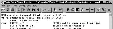
 From the Serial Port Settings window, you can
click the View Button under IDE/SBC Transactions to view the status of
communications between the SBC and the Vesta Basic IDE.
From the Serial Port Settings window, you can
click the View Button under IDE/SBC Transactions to view the status of
communications between the SBC and the Vesta Basic IDE.