The VADC12 provides eight single-end or four differential 12-bit analog to digital converter inputs capable of measuring voltages between 0 and 4.095 VDC with a resolution of one part in 4096. The VAIO12 adds four 12-bit analog output channels.
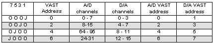
1. Install ADDR jumpers to pins 1-2 (as shipped). This puts the board at VAST address 0, with:
2. Install a jumper between pin 3 of the AOUT connector and pin 3 of the AIN connector. This connects channel 0 of the D/A to channel 0 of the A/D.
3. Connect the VAST cable to the SBC2000.
4. Apply power to the SBC2000 and execute the following code:
CONSTANT CRLF AS STRING = "\010\013"
GLOBAL value AS INTEGER

VAIN_CONFIG(0,2)
VAOUT_CONFIG(0,2)
DO
	PRINT CRLF
	FOR value = 0 TO 4096 STEP 64
		VAOUT(0, value)
		PRINT VAIN(0)
	NEXT
LOOP UNTIL 0 AIN() reads the specified channel. Valid channels are 0 to 31. Return result is 0 to 4095. AIN_CONFIG() configures extensions for running analog to digital conversions. Func determines which parameter is being configured. Value sets up the parameter selected by func. When the VAIO12/VADC12 is selected using func=0, the rest of the conversion parameters are automatically set to a default configuration. AOUT_CONFIG() sets the type of peripheral to use for digital to analog conversions. Func should always be zero. To configure the extensions to use the VAIO12/VADC12, call AOUT_CONFIG() with a value argument set to 2. There is no need to call the AOUT_CONFIG() before every conversion. Once extensions are configured, they will remain so until changed. AOUT() sets the specified D/A output to the specified value. Channels range from 0 to 15. Data values range from 0 to 4095.
| Func | Setting | Value | Configuration |
| 0 | Select Peripheral | 2 | Selects VAIO12/VADC12 |
| 1 | Input Organization | 0 | AIN0-7 are single ended input (default) |
| 1 | AIN0-1, 2-3,4-5 and 6-7 are differential pairs | ||
| 2 | Polarity | 0 | Unipolar (default) |
| 1 | Bipolar | ||
| 4 | Powerdown mode | 0 | Full Powerdown |
| 1 | Standby Powerdown | ||
| 2 | Normal (default) |
Note that this board takes two adjacent VAST addresses (one for the A/D, one for the D/A), and that these VAST addresses must be in the range from 0 through 7.
| Pin | Signal | Pin | Signal |
| 1 | AGND | 2 | +5V |
| 3 | AIN0 | 4 | AIN1 |
| 5 | AIN2 | 6 | AIN3 |
| 7 | AIN4 | 8 | AIN5 |
| 9 | AIN6 | 10 | AIN7 |
| Pin | Function | Pin | Function |
| 1 | AGND | 2 | +5V |
| 3 | AOUT0 | 4 | AOUT1 |
| 5 | AOUT2 | 6 | AOUT4 |
| 7 | REF01 | 8 | REF23 |
The trimpot marked "ADC_CAL" is used to trim the reference of the A/D. Calibration range is 2%. While inputting a known voltage, trim until the result in millivolts or bits is equal to the input.
The trimpots marked "DAC 01 CAL" and "DAC 23 CAL" calibrate D/A channels 0, 1 and 2, 3 respectively. The D/As may be calibrated through a much larger range than the ADC. Calibrate by setting the DAC to 4095 and adjust the trimpot for 2.048 Volts or the desired full scale output. Output voltages greater than 3.6 Volts will depend on the load and Vcc.
The analog inputs represent a DC load of 1 Meg Ohm. However, the AC impedance is significantly lower. Inputs should be driven from a low impedance source or a large (0.1 uF) capacitor placed from the input to ground.
Each D/A is buffered with an internal operational amplifier. These op amps can drive 3.6 volts into a 10k Ohm load with negligible error. A 1k Ohm load will produce 1 LSB of error.
The VAIO12 requires 3 milliamperes at 5 VDC.
Dimensions are in inches.